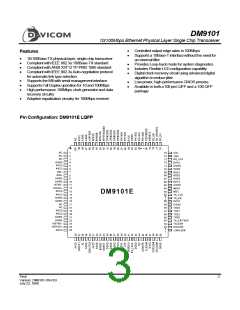
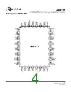
DM9101
10/100Mbps Ethernet Physical Layer Single Chip Transceiver
Pin Description (continued)
Pin No.
LQFP QFP
LED Interface :
These outputs can directly drive LEDs or provide status information to a network management device.
Pin Name
I/O
Description
Polarity/Full Duplex LED:
48
50
FDXLED#
(POLLED)
O
Indicates Full Duplex mode status for 100Mbps and 10Mbps
operation (Active low). If bit 4 of Register 16 (FDXLED_MODE) is
set, the FDXLED# pin function will change to indicate the Polarity
status for 10Mbps operation. If polarity is inverted, the POLLED
will go ON.
Collision LED:
49
51
51
53
COLLED#
O
O
Indicates the presence of collision activity for 10Mbps and
100Mbps operation. This LED has no meaning for 10Mbps or
100Mbps Full Duplex operation (Active low).
Link LED:
Indicates Good Link status for 10Mbps and 100Mbps operation
(Active low).
LINKLED#
(TRAFFIC
LED)
It functions as the TRAFFIC LED when bit 5 of register 16 is set
to 1. In TRAFFIC LED mode, it is always ON when the link is OK.
The TRAFFIC LED flashes when transmitting or receiving.
Receive LED:
Indicates the presence of receive activity for 10Mbps and
100Mbps operation (Active low).
The DM9101 incorporates a "monostable" function on the RXLED
output. This ensures that even minimal receive activity will
generate an adequate LED ON time.
52
53
54
55
RXLED#
TXLED#
OD
OD
Transmit LED:
Indicates the presence of transmit activity for 10Mbps and
100Mbps operation (Active low).
The DM9101 incorporates a "monostable" function on the TXLED
output. This ensures that even minimal transmit activity will
generate an adequate LED ON time.
Device Configuration/Control/Status Interface
UTP Cable Indication:
40
42
UTP
O
UTP=1: Indicates UTP cable is used.
Speed 10Mbps:
41
43
SPEED10
O
When set high, this bit indicates a 10Mbps operation, when set
low 100Mbps operation. This pin can drive a low current LED to
indicate that 100Mbps operation is selected.
Lock for Clock/Data Recovery PLL:
When this pin is high it indicates that the receiver recovery PLL
logic has locked to the input data stream.
Link Status Register Bit:
42
45
44
47
RX_LOCK
LINKSTS
O
O
This pin reflects the status of bit 2 register 1.
Final
7
Version: DM9101-DS-F03
July 22, 1999

 ETC [ ETC ]