ST72104G, ST72215G, ST72216G, ST72254G
SERIAL PERIPHERAL INTERFACE (Cont’d)
12.3.4.5 Master Mode Fault
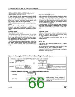
may be restored to their original state during or af-
ter this clearing sequence.
Master mode fault occurs when the master device
has its SS pin pulled low, then the MODF bit is set.
Hardware does not allow the user to set the SPE
and MSTR bits while the MODF bit is set except in
the MODF bit clearing sequence.
Master mode fault affects the SPI peripheral in the
following ways:
In a slave device the MODF bit can not be set, but
in a multi master configuration the device can be in
slave mode with this MODF bit set.
– The MODF bit is set and an SPI interrupt is
generated if the SPIE bit is set.
– The SPE bit is reset. This blocks all output
from the device and disables the SPI periph-
eral.
The MODF bit indicates that there might have
been a multi-master conflict for system control and
allows a proper exit from system operation to a re-
set or default system state using an interrupt rou-
tine.
– The MSTR bit is reset, thus forcing the device
into slave mode.
Clearing the MODF bit is done through a software
sequence:
12.3.4.6 Overrun Condition
An overrun condition occurs when the master de-
vice has sent several data bytes and the slave de-
vice has not cleared the SPIF bit issuing from the
previous data byte transmitted.
1. A read or write access to the SR register while
the MODF bit is set.
2. A write to the CR register.
In this case, the receiver buffer contains the byte
sent after the SPIF bit was last cleared. A read to
the DR register returns this byte. All other bytes
are lost.
Notes: To avoid any multiple slave conflicts in the
case of a system comprising several MCUs, the
SS pin must be pulled high during the clearing se-
quence of the MODF bit. The SPE and MSTR bits
This condition is not detected by the SPI peripher-
al.
67/140

 ETC [ ETC ]