ST72104G, ST72215G, ST72216G, ST72254G
9 POWER SAVING MODES
9.1 INTRODUCTION
9.2 SLOW MODE
To give a large measure of flexibility to the applica-
tion in terms of power consumption, three main
power saving modes are implemented in the ST7
(see Figure 16).
This mode has two targets:
– To reduce power consumption by decreasing the
internal clock in the device,
– To adapt the internal clock frequency (f
the available supply voltage.
) to
CPU
After a RESET the normal operating mode is se-
lected by default (RUN mode). This mode drives
the device (CPU and embedded peripherals) by
means of a master clock which is based on the
SLOW mode is controlled by three bits in the
MISCR1 register: the SMS bit which enables or
disables Slow mode and two CPx bits which select
main oscillator frequency divided by 2 (f
).
CPU
the internal slow frequency (f
).
CPU
From Run mode, the different power saving
modes may be selected by setting the relevant
register bits or by calling the specific ST7 software
instruction whose action depends on the oscillator
status.
In this mode, the oscillator frequency can be divid-
ed by 4, 8, 16 or 32 instead of 2 in normal operat-
ing mode. The CPU and peripherals are clocked at
this lower frequency.
Note: SLOW-WAIT mode is activated when enter-
ing WAIT mode while the device is already in
SLOW mode.
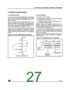
Figure 16. Power Saving Mode Transitions
High
RUN
Figure 17. SLOW Mode Clock Transitions
f
/4
f
/8
f
/2
OSC
OSC
OSC
f
CPU
SLOW
WAIT
f
/2
OSC
00
01
CP1:0
SMS
SLOW WAIT
HALT
NORMAL RUN MODE
REQUEST
NEW SLOW
FREQUENCY
REQUEST
Low
POWER CONSUMPTION
27/140

 ETC [ ETC ]