ST72104G, ST72215G, ST72216G, ST72254G
10 I/O PORTS
10.1 INTRODUCTION
programmable using the sensitivity bits in the Mis-
cellaneous register.
The I/O ports offer different functional modes:
– transfer of data through digital inputs and outputs
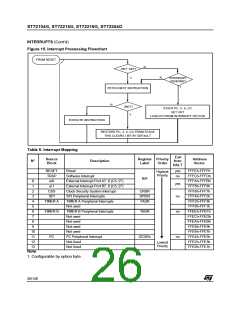
Each external interrupt vector is linked to a dedi-
cated group of I/O port pins (see pinout description
and interrupt section). If several input pins are se-
lected simultaneously as interrupt source, these
are logically ANDed. For this reason if one of the
interrupt pins is tied low, it masks the other ones.
and for specific pins:
– external interrupt generation
– alternate signal input/output for the on-chip pe-
ripherals.
An I/O port contains up to 8 pins. Each pin can be
programmed independently as digital input (with or
without interrupt generation) or digital output.
In case of a floating input with interrupt configura-
tion, special care must be taken when changing
the configuration (see Figure 22).
The external interrupts are hardware interrupts,
which means that the request latch (not accessible
directly by the application) is automatically cleared
when the corresponding interrupt vector is
fetched. To clear an unwanted pending interrupt
by software, the sensitivity bits in the Miscellane-
ous register must be modified.
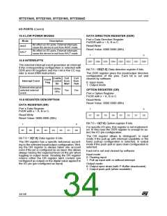
10.2 FUNCTIONAL DESCRIPTION
Each port has 2 main registers:
– Data Register (DR)
– Data Direction Register (DDR)
and one optional register:
– Option Register (OR)
10.2.2 Output Modes
The output configuration is selected by setting the
corresponding DDR register bit. In this case, writ-
ing the DR register applies this digital value to the
I/O pin through the latch. Then reading the DR reg-
ister returns the previously stored value.
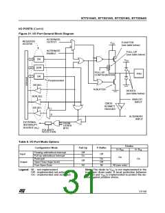
Each I/O pin may be programmed using the corre-
sponding register bits in the DDR and OR regis-
ters: bit X corresponding to pin X of the port. The
same correspondence is used for the DR register.
The following description takes into account the
OR register, (for specific ports which do not pro-
vide this register refer to the I/O Port Implementa-
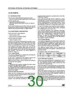
tion section). The generic I/O block diagram is
shown in Figure 21
Two different output modes can be selected by
software through the OR register: Output push-pull
and open-drain.
DR register value and output pin status:
10.2.1 Input Modes
DR
0
Push-pull
Open-drain
Vss
V
The input configuration is selected by clearing the
corresponding DDR register bit.
SS
1
V
Floating
DD
In this case, reading the DR register returns the
digital value applied to the external I/O pin.
10.2.3 Alternate Functions
When an on-chip peripheral is configured to use a
pin, the alternate function is automatically select-
ed. This alternate function takes priority over the
standard I/O programming.
Different input modes can be selected by software
through the OR register.
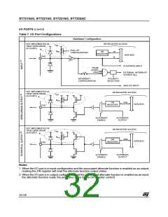
Notes:
1. Writing the DR register modifies the latch value
but does not affect the pin status.
When the signal is coming from an on-chip periph-
eral, the I/O pin is automatically configured in out-
put mode (push-pull or open drain according to the
peripheral).
2. When switching from input to output mode, the
DR register has to be written first to drive the cor-
rect level on the pin as soon as the port is config-
ured as an output.
When the signal is going to an on-chip peripheral,
the I/O pin must be configured in input mode. In
this case, the pin state is also digitally readable by
addressing the DR register.
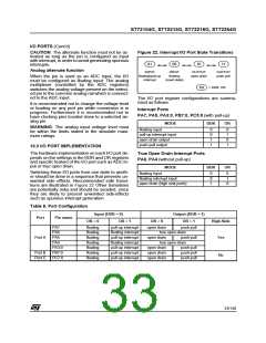
External interrupt function
When an I/O is configured as Input with Interrupt,
an event on this I/O can generate an external inter-
rupt request to the CPU.
Note: Input pull-up configuration can cause unex-
pected value at the input of the alternate peripheral
input. When an on-chip peripheral use a pin as in-
put and output, this pin has to be configured in in-
put floating mode.
Each pin can independently generate an interrupt
request. The interrupt sensitivity is independently
30/140

 ETC [ ETC ]