ST72104G, ST72215G, ST72216G, ST72254G
POWER SAVING MODES (Cont’d)
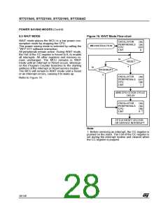
9.3 WAIT MODE
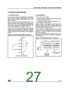
Figure 18. WAIT Mode Flow-chart
WAIT mode places the MCU in a low power con-
sumption mode by stopping the CPU.
This power saving mode is selected by calling the
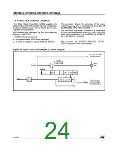
OSCILLATOR
PERIPHERALS
CPU
I BIT
ON
ON
OFF
0
WFI INSTRUCTION
“WFI” ST7 software instruction.
All peripherals remain active. During WAIT mode,
the I bit of the CC register is forced to 0, to enable
all interrupts. All other registers and memory re-
main unchanged. The MCU remains in WAIT
mode until an interrupt or Reset occurs, whereup-
on the Program Counter branches to the starting
address of the interrupt or Reset service routine.
The MCU will remain in WAIT mode until a Reset
or an Interrupt occurs, causing it to wake up.
N
RESET
Y
N
INTERRUPT
Y
OSCILLATOR
PERIPHERALS
CPU
ON
OFF
ON
1
Refer to Figure 18.
I BIT
4096 CPU CLOCK CYCLE
DELAY
OSCILLATOR
PERIPHERALS
CPU
ON
ON
ON
1)
I BIT
X
FETCH RESET VECTOR
OR SERVICE INTERRUPT
Note:
1. Before servicing an interrupt, the CC register is
pushed on the stack. The I bit of the CC register is
set during the interrupt routine and cleared when
the CC register is popped.
28/140

 ETC [ ETC ]