ST72104G, ST72215G, ST72216G, ST72254G
8 INTERRUPTS
The ST7 core may be interrupted by one of two dif-
ferent methods: maskable hardware interrupts as
listed in the Interrupt Mapping Table and a non-
maskable software interrupt (TRAP). The Interrupt
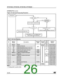
processing flowchart is shown in Figure 1.
The maskable interrupts must be enabled clearing
the I bit in order to be serviced. However, disabled
interrupts may be latched and processed when
they are enabled (see external interrupts subsec-
tion).
It will be serviced according to the flowchart on
Figure 1.
8.2 EXTERNAL INTERRUPTS
External interrupt vectors can be loaded into the
PC register if the corresponding external interrupt
occurred and if the I bit is cleared. These interrupts
allow the processor to leave the Halt low power
mode.
When an interrupt has to be serviced:
The external interrupt polarity is selected through
the miscellaneous register or interrupt register (if
available).
– Normal processing is suspended at the end of
the current instruction execution.
An external interrupt triggered on edge will be
latched and the interrupt request automatically
cleared upon entering the interrupt service routine.
– The PC, X, A and CC registers are saved onto
the stack.
– The I bit of the CC register is set to prevent addi-
tional interrupts.
If several input pins, connected to the same inter-
rupt vector, are configured as interrupts, their sig-
nals are logically ANDed before entering the edge/
level detection block.
– The PC is then loaded with the interrupt vector of
the interrupt to service and the first instruction of
the interrupt service routine is fetched (refer to
the Interrupt Mapping Table for vector address-
es).
Caution: The type of sensitivity defined in the Mis-
cellaneous or Interrupt register (if available) ap-
plies to the ei source. In case of an ANDed source
(as described on the I/O ports section), a low level
on an I/O pin configured as input with interrupt,
masks the interrupt request even in case of rising-
edge sensitivity.
The interrupt service routine should finish with the
IRET instruction which causes the contents of the
saved registers to be recovered from the stack.
Note: As a consequence of the IRET instruction,
the I bit will be cleared and the main program will
resume.
8.3 PERIPHERAL INTERRUPTS
Priority Management
Different peripheral interrupt flags in the status
register are able to cause an interrupt when they
are active if both:
By default, a servicing interrupt cannot be inter-
rupted because the I bit is set by hardware enter-
ing in interrupt routine.
– The I bit of the CC register is cleared.
In the case when several interrupts are simultane-
ously pending, an hardware priority defines which
one will be serviced first (see the Interrupt Map-
ping Table).
– The corresponding enable bit is set in the control
register.
If any of these two conditions is false, the interrupt
is latched and thus remains pending.
Interrupts and Low Power Mode
Clearing an interrupt request is done by:
All interrupts allow the processor to leave the
WAIT low power mode. Only external and specifi-
cally mentioned interrupts allow the processor to
leave the HALT low power mode (refer to the “Exit
from HALT“ column in the Interrupt Mapping Ta-
ble).
– Writing “0” to the corresponding bit in the status
register or
– Access to the status register while the flag is set
followed by a read or write of an associated reg-
ister.
Note: the clearing sequence resets the internal
latch. A pending interrupt (i.e. waiting for being en-
abled) will therefore be lost if the clear sequence is
executed.
8.1 NON MASKABLE SOFTWARE INTERRUPT
This interrupt is entered when the TRAP instruc-
tion is executed regardless of the state of the I bit.
25/140

 ETC [ ETC ]