a-Si TFT LCD Single Chip Driver
240RGBx320 Resolution and 262K color
ILI9325
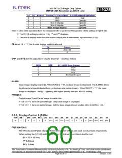
D1 D0 BASEE Source, VCOM Output ILI9325 internal operation
0
0
1
1
1
0
1
0
1
1
0
1
0
0
1
GND
GND
Halt
Operate
Operate
Operate
Operate
Non-lit display
Non-lit display
Base image display
Note: 1. data write operation from the microcontroller is performed irrespective of the setting of D[1:0] bits.
2. The D[1:0] setting is valid on both 1st and 2nd displays.
3. The non-lit display level from the source output pins is determined by instruction (PTS).
CL When CL = “1”, the 8-color display mode is selected.
CL
0
1
Colors
262,144
8
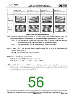
GON and DTE Set the output level of gate driver G1 ~ G320 as follows
GON
DTE
G1 ~G320 Gate Output
0
0
1
1
0
1
0
1
VGH
VGH
VGL
Normal Display
BASEE
Base image display enable bit. When BASEE = “0”, no base image is displayed. The ILI9325 drives
liquid crystal at non-lit display level or displays only partial images. When BASEE = “1”, the base
image is displayed. The D[1:0] setting has higher priority over the BASEE setting.
PTDE[1:0]
Partial image 2 and Partial image 1 enable bits
PTDE1/0 = 0: turns off partial image. Only base image is displayed.
PTDE1/0 = 1: turns on partial image. Set the base image display enable bit to 0 (BASEE = 0).
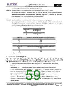
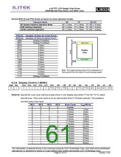
8.2.8. Display Control 2 (R08h)
R/W RS
D15 D14 D13 D12 D11 D10 D9
D8 D7 D6 D5 D4 D3
D2
D1
D0
W
1
0
0
0
0
FP3
FP2 FP1 FP0
0
0
0
0
BP3 BP2 BP1 BP0
FP[3:0]/BP[3:0]
The FP[3:0] and BP[3:0] bits specify the line number of front and back porch periods respectively.
When setting the FP[3:0] and BP[3:0] value, the following conditions shall be met:
BP + FP ≤ 16 lines
FP ≥ 2 lines
BP ≥ 2 lines
The information contained herein is the exclusive property of ILI Technology Corp. and shall not be distributed,
reproduced, or disclosed in whole or in part without prior written permission of ILI Technology Corp.
Page 60 of 111
Version: 0.35

 ETC [ ETC ]