a-Si TFT LCD Single Chip Driver
240RGBx320 Resolution and 262K color
ILI9325
100
101
110
111
5 Frames
6 Frames
7 Frames
8 Frames
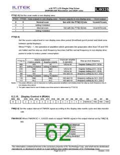
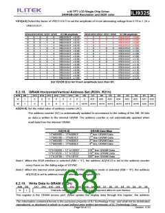
8.2.12. Frame Marker Position (R0Dh)
R/W RS
D15 D14 D13 D12 D11 D10 D9
D8
D7
D6
D5
D4
D3
D2
D1
D0
W
1
0
0
0
0
0
0
0
FMP8 FMP7 FMP6 FMP5 FMP4 FMP3 FMP2 FMP1 FMP0
EMP[8:0] Sets the output position of frame cycle (frame marker).
When FMP[8:0]=0, a high-active pulse FMARK is output at the start of back porch period for one display line
period (1H).
Make sure the 9’h000 ≦ FMP ≦ BP+NL+FP
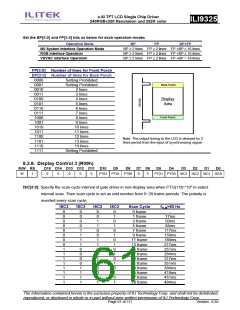
FMP[8:0]
9’h000
9’h001
9’h002
9’h003
.
FMARK Output Position
0th line
1st line
2nd line
3rd line
.
.
.
.
.
9’h175
9’h176
9’h177
373rd line
374th line
375th line
8.2.13. RGB Display Interface Control 2 (R0Fh)
R/W
RS
D15
D14
D13
D12
D11
D10
D9
D8
D7
D6
D5
D4
D3
D2
D1
D0
W
1
0
0
0
0
0
0
0
0
0
0
0
VSPL
HSPL
0
EPL
DPL
DPL: Sets the signal polarity of the DOTCLK pin.
DPL = “0” The data is input on the rising edge of DOTCLK
DPL = “1” The data is input on the falling edge of DOTCLK
EPL: Sets the signal polarity of the ENABLE pin.
EPL = “0” The data DB17-0 is written when ENABLE = “0”. Disable data write operation when
ENABLE = “1”.
EPL = “1” The data DB17-0 is written when ENABLE = “1”. Disable data write operation when
ENABLE = “0”.
HSPL: Sets the signal polarity of the HSYNC pin.
HSPL = “0” Low active
HSPL = “1” High active
VSPL: Sets the signal polarity of the VSYNC pin.
VSPL = “0” Low active
VSPL = “1” High active
The information contained herein is the exclusive property of ILI Technology Corp. and shall not be distributed,
reproduced, or disclosed in whole or in part without prior written permission of ILI Technology Corp.
Page 64 of 111
Version: 0.35

 ETC [ ETC ]