a-Si TFT LCD Single Chip Driver
240RGBx320 Resolution and 262K color
ILI9325
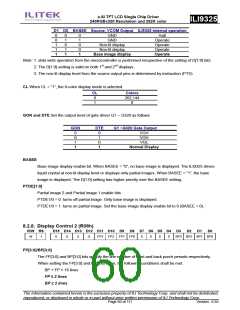
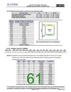
Set the BP[3:0] and FP[3:0] bits as below for each operation modes
Operation Mode
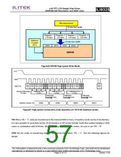
I80 System Interface Operation Mode
RGB interface Operation
BP
FP
BP+FP
BP ≥ 2 lines FP ≥ 2 lines FP +BP ≤ 16 lines
BP ≥ 2 lines FP ≥ 2 lines FP +BP ≤ 16 lines
BP ≥ 2 lines FP ≥ 2 lines FP +BP = 16 lines
VSYNC interface Operation
FP[3:0] Number of lines for Front Porch
BP[3:0] Number of lines for Back Porch
0000
0001
0010
0011
0100
0101
0110
0111
1000
1001
1010
1011
1100
1101
1110
1111
Setting Prohibited
Setting Prohibited
2 lines
Back Porch
3 lines
4 lines
5 lines
6 lines
7 lines
8 lines
9 lines
10 lines
11 lines
12 lines
13 lines
14 lines
Display
Area
Front Porch
Note: The output timing to the LCD is delayed by 2
lines period from the input of synchronizing signal.
Setting Prohibited
8.2.9. Display Control 3 (R09h)
R/W RS
D15 D14 D13 D12 D11 D10
D9
D8
D7 D6
D5
D4
D3
D2
D1
D0
W
1
0
0
0
0
0
PTS2 PTS1 PTS0
0
0
PTG1 PTG0 ISC3 ISC2 ISC1 ISC0
ISC[3:0]: Specify the scan cycle interval of gate driver in non-display area when PTG[1:0]=”10” to select
interval scan. Then scan cycle is set as odd number from 0~29 frame periods. The polarity is
inverted every scan cycle.
ISC3
0
ISC3
0
ISC3
0
ISC3
0
Scan Cycle
0 frame
f
FLM=60 Hz
-
0
0
0
1
1 frame
17ms
0
0
1
0
3 frame
50ms
0
0
1
1
5 frame
84ms
0
0
0
0
1
1
1
1
1
1
1
1
1
1
1
1
0
0
0
0
1
1
1
1
0
0
1
1
0
0
1
1
0
0
1
1
0
1
0
1
0
1
0
1
0
1
0
1
7 frame
9 frame
117ms
150ms
184ms
217ms
251ms
284ms
317ms
351ms
384ms
418ms
451ms
484ms
11 frame
13 frame
15 frame
17 frame
19 frame
21 frame
23 frame
25 frame
27 frame
29 frame
The information contained herein is the exclusive property of ILI Technology Corp. and shall not be distributed,
reproduced, or disclosed in whole or in part without prior written permission of ILI Technology Corp.
Page 61 of 111
Version: 0.35

 ETC [ ETC ]