a-Si TFT LCD Single Chip Driver
240RGBx320 Resolution and 262K color
ILI9325
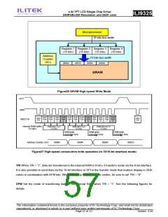
Microprocessor
18 bits bus width
Register 1 Register 2 Register 3 Register 4
(18 bits)
(18 bits)
(18 bits)
(18 bits)
Address
Counter
(AC)
72 bits bus width
0000h
0001h
0002h
0003h
GRAM
Figure26 GRAM High-speed Write Mode
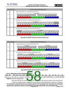
nCS
nWR
RAM RAM RAM RAM RAM RAM RAM RAM RAM RAM RAM RAM
Data Data Data Data Data Data Data Data Data Data Data Data
Index
R22
Index
R22
DB[17:0]
1
2
3
4
5
6
7
8
9
10
11
12
Internal RAM buffer
(72 bits)
RAM data 1 to 4
(72 bits)
RAM data 5 to 8
(72 bits)
RAM data 9 to 12
(72 bits)
RAM write
RAM write
RAM write
execution time
execution time
execution time
Address Counter (AC)
0000h
0004h
0008h
000Ch
Figure27 High-speed consecutive write operation (in 18/16-bit interface mode)
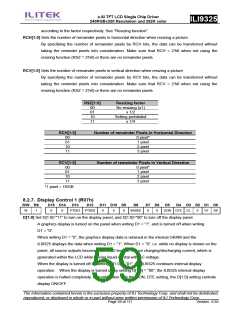
TRI When TRI = “1”, data are transferred to the internal RAM in 8-bit x 3 transfers mode via the 8-bit interface.
It is also possible to send data via the 16-bit interface or SPI in the transfer mode that realizes display in 262k
colors in combination with DFM bits. When not using these interface modes, be sure to set TRI = “0”.
DFM Set the mode of transferring data to the internal RAM when TRI = “1”. See the following figures for
details.
The information contained herein is the exclusive property of ILI Technology Corp. and shall not be distributed,
reproduced, or disclosed in whole or in part without prior written permission of ILI Technology Corp.
Page 57 of 111
Version: 0.35

 ETC [ ETC ]