a-Si TFT LCD Single Chip Driver
240RGBx320 Resolution and 262K color
ILI9325
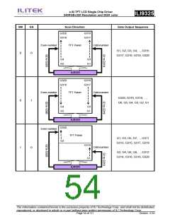
G320
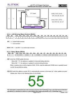
Even-number
TFT Panel
G320, G318, G316, …,
G10, G8, G6, G4, G2
G2
G319
G1
Odd-number
1
1
G319, G317, G315, …,
G9, G78, G5, G3, G1
ILI9325
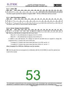
8.2.4. LCD Driving Wave Control (R02h)
R/W RS
D15 D14 D13 D12 D11 D10
D9
D8
D7 D6 D5 D4 D3 D2 D1 D0
W
1
0
0
0
0
0
1
B/C
EOR
0
0
0
0
0
0
0
0
.B/C 0 : Frame/Field inversion
1 : Line inversion
EOR: EOR = 1 and B/C=1 to set the line inversion.
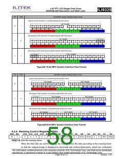
8.2.5. Entry Mode (R03h)
R/W RS
D15 D14 D13 D12 D11 D10
D9
D8
D7
D6 D5
D4 D3 D2 D1 D0
W
1
TRI
DFM
0
BGR
0
0
HWM
0
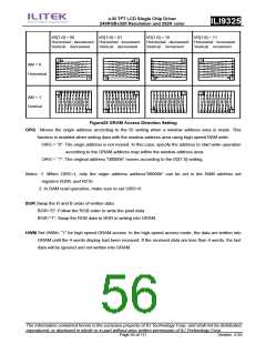
ORG
0
I/D1 I/D0 AM
0
0
0
AM Control the GRAM update direction.
When AM = “0”, the address is updated in horizontal writing direction.
When AM = “1”, the address is updated in vertical writing direction.
When a window area is set by registers R50h ~R53h, only the addressed GRAM area is updated based
on I/D[1:0] and AM bits setting.
I/D[1:0] Control the address counter (AC) to automatically increase or decrease by 1 when update one pixel
display data. Refer to the following figure for the details.
The information contained herein is the exclusive property of ILI Technology Corp. and shall not be distributed,
reproduced, or disclosed in whole or in part without prior written permission of ILI Technology Corp.
Page 55 of 111
Version: 0.35

 ETC [ ETC ]