Data Sheet
June 1999
ORCA Series 2 FPGAs
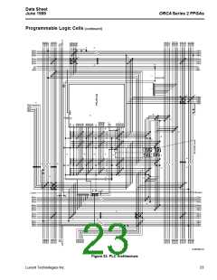
N. These are the 11 logic inputs to the LUT. The A[4:0]
inputs are provided into HLUTA, and the B[4:0]
inputs are provided into HLUTB. The C0 input
bypasses the main LUT and is used in the pfumux,
pfuxor, and pfunand functions (F5M, F5X modes).
Since this input bypasses the LUT, it can be used as
a fast path around the LUT, allowing the implemen-
tation of fast, wide combinatorial functions. The C0
input can be disabled or inverted.
Programmable Logic Cells (continued)
J. Any five of the eight output signals can be routed out
of the PLC. The eight signals are the four LUT out-
puts (F0, F1, F2, and F3) and the four latch/FF out-
puts (Q0, Q1, Q2, and Q3). This allows the user to
access all four latch/FF outputs, read the present
state and next state of a latch/FF, build a 4-bit shift
register, etc. Each of the outputs can drive any num-
ber of the five PFU outputs. The speed of a signal
can be increased by dividing its load among multiple
PFU output drivers.
O. The XH lines run one-half the length (width) of the
array before being broken by a CIP.
P. The BIDIHs are used to access the XH lines.
K. These lines deliver the auxiliary signals’ clock
enable and set/reset to the latches/FFs. All four of
the latches/FFs share these signals.
Q.The BIDIH lines are used to connect the BIDIHs to
the XSW lines, the XH lines, or the BIDI lines.
R. These CIPs connect the BIDI lines and the BIDIH
L. This is the clock input to the latches/FFs. Any of the
horizontal and vertical XH or XL lines can drive the
clock of the PLC latches/FFs. Long-line drivers are
provided so that a PLC can drive one XL line in the
horizontal direction and one XL line in the vertical
direction. The XL lines in each direction exhibit the
same properties as X4 lines, except there are no
CIPs. The clock lines (CKL, CKR, CKT, and CKB)
and multiplexers/drivers are used to connect to the
XL lines for low-skew, low-delay global signals.
lines.
S. These are clock lines (CKT, CKB, CKL, and CKR)
with the multiplexers and drivers to connect to the
XL lines.
T. These CIPs connect X1 lines which cross in each
corner to allow turns on the X1 lines without using
the XSW lines.
U. These CIPs connect X4 lines and xsw lines, allowing
nets that run a distance that is not divisible by four to
be routed more efficiently.
The long lines run the length or width of the PLC
array. They rotate to allow four PLCs in one row or
column to generate four independent global signals.
These lines do not have to be used for clock routing.
Any highly used application net can use this
resource, especially one requiring low skew.
V. This routing structure allows any PFU output, includ-
ing LUT and latch/FF outputs, to be placed on O4
and be routed onto the fast carry routing.
W.This routing structure allows the fast carry routing to
M.These lines are used to route the fast carry signal to/
from the neighboring four PLCs. The carry-out
(COUT) of the PFU can also be routed out of the
PFU onto the fifth output (O4). The carry-in (CIN)
signal can also be supplied by the B4 input to the
PFU.
be routed onto the C0 PFU input.
24
Lucent Technologies Inc.

 ETC [ ETC ]