Data Sheet
June 1999
ORCA Series 2 FPGAs
The clock lines are designed to be a clock spine. In
Programmable Logic Cells (continued)
each PLC, there is a fast connection available from the
clock line to the long-line driver (described earlier).
With this connection, one of the clock lines in each PLC
can be used to drive one of the four XL lines perpendic-
ular to it, which, in turn, creates a clock tree.
XL Lines. The long XL lines run vertically and horizon-
tally the height and width of the array, respectively.
There are a total of eight XL lines per PLC: four hori-
zontal (HXL[3:0]) and four vertical (VXL[3:0]). Each
PLC column has four XL lines, and each PLC row has
four XL lines. Each of the XL lines connects to the two
PICs at either end. The Series 2, which consists of a
18 x 18 array of PLCs, contains 72 VXL and 72 HXL
lines. They are intended primarily for global signals
which must travel long distances and require minimum
delay and/or skew, such as clocks.
This feature is discussed in detail in the Clock Distribu-
tion Network section.
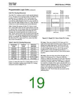
Minimizing Routing Delay
The CIP is an active element used to connect two lines.
As an active element, it adds significantly to the resis-
tance and capacitance of a net, thus increasing the
net’s delay. The advantage of the X1 line over a X4 line
is routing flexibility. A net from PLC db to PLC cb is eas-
ily routed by using X1 lines. As more CIPs are added to
a net, the delay increases. To increase speed, routes
that are greater than two PLCs away are routed on the
X4 lines because a CIP is located only in every fourth
PLC. A net that spans eight PLCs requires seven X1
lines and six CIPs. Using X4 lines, the same net uses
two lines and one CIP.
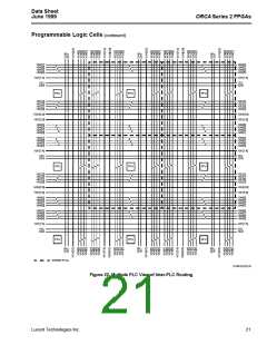
There are three methods for routing signals onto the XL
lines. In each PLC, there are two long-line drivers: one
for a horizontal XL line, and one for a vertical XL line.
Using the long-line drivers produces the least delay.
The XL lines can also be driven directly by PFU outputs
using the BIDI lines. In the third method, the XL lines
are accessed by the bidirectional buffers, again using
the BIDI lines.
XH Lines. Four by half (XH) lines run horizontally and
four XH lines run vertically in each row and column in
the array. These lines travel a distance of one-half the
PLC array before being broken in the middle of the
array, where they connect to the interquad block (dis-
cussed later). They also connect at the periphery of the
FPGA to the PICs, like the XL lines. The XH lines do
not twist like XL lines, allowing nibble-wide buses to be
routed easily.
All routing resources in the PLC can carry 4-bit buses.
In order for data to be used at a destination PLC that is
in data path mode, the data must arrive unscrambled.
For example, in data path operation, the least signifi-
cant bit 0 must arrive at either A[0] or B[0]. If the bus is
to be routed by using either X4 or XL lines (both of
which twist as they propagate), the bus must be placed
on the appropriate lines at the source PLC so that the
data arrives at the destination unscrambled. The
switching lines provide the most efficient means of con-
necting adjacent PLCs. Signals routed with these lines
have minimum propagation delay.
Two of the three methods of routing signals onto the
XL lines can also be used for the XH lines. A special
XH line driver is not supplied for the XH lines.
Clock Lines. For a very fast and low-skew clock (or
other global signal tree), clock lines run the entire
height and width of the PLC array. There are two hori-
zontal clock lines per PLC row (CKL, CKR) and two
vertical clock lines per PLC column (CKT, CKB). The
source for these clock lines can be any of the four I/O
buffers in the PIC. The horizontal clock lines in a row
(CKL, CKR) are driven by the left and right PICs,
respectively. The vertical clock lines in a column (CKT,
CKB) are driven by the top and bottom PICs, respec-
tively.
20
Lucent Technologies Inc.

 ETC [ ETC ]