Data Sheet
June 1999
ORCA Series 2 FPGAs
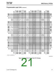
D. The X4 lines are twisted at each PLC. One of the
four X4 lines is broken with a CIP, which allows a sig-
nal to be routed a distance of four PLCs in any direc-
tion on a single line without an intermediate CIP. The
X4 lines are less populated with CIPs than the X1
lines to increase their speed. A CIP can be enabled
to extend an X4 line four more PLCs, and so on.
Programmable Logic Cells (continued)
PLC Architectural Description
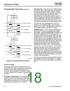
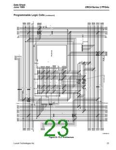
Figure 23 is an architectural drawing of the PLC which
reflects the PFU, the lines, and the CIPs. A discussion
of each of the letters in the drawing follows.
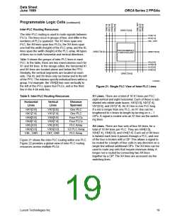
For example, if an application signal is routed onto
HX4[4] in a PLC, it appears on HX4[5] in the PLC to
the right. This signal step-up continues until it
reaches HX4[7], two PLCs later. At this point, the
user can break the connection or continue the signal
for another four PLCs.
A. These are switching lines which give the router flexi-
bility. In general switching theory, the more levels of
indirection there are in the routing, the more routable
the network is. The switching lines can also connect
to adjacent PLCs.
The switching lines provide direct connections to
PLCs directly to the top, bottom, left, and right, with-
out using other routing resources. The ability to dis-
able this connection between PLCs is provided so
that each side of these connections can be used
exclusively as switching lines in their respective
PLC.
E. These symbols are bidirectional buffers (BIDIs).
There are four BIDIs per PLC, and they provide sig-
nal amplification as needed to decrease signal
delay. The BIDIs are also used to transmit signals on
XL lines.
F. These are the BIDI and BIDIH controllers. The 3-
state control signal can be disabled. They can be
configured as active-high or active-low indepen-
dently of each other.
B. These CIPs connect the X1 routing. These are
located in the middle of the PLC to allow the block to
connect to either the left end of the horizontal X1 line
from the right or the right end of the horizontal X1
line from the left, or both. By symmetry, the same
principle is used in the vertical direction. The X1
lines are not twisted, making them suitable for data
paths.
G.This set of CIPs allows a BIDI to get or put a signal
from one set of switching lines on each side. The
BIDIs can be accessed by the switching lines. These
CIPs allow a nibble of data to be routed though the
BIDIs and continue to a subsequent block. They also
provide an alternative routing resource to improve
routability.
C. This set of CIPs is used to connect the X1 and X4
nets to the switching lines or to other X1 and X4
nets. The CIPs on the major diagonal allow data to
be transmitted from X1 nets to the switching lines
without being scrambled. The CIPs on the major
diagonal also allow unscrambled data to be passed
between the X1 and X4 nets.
H.These CIPs are used to take data from/to the BIDIs
to/from the XL lines. These CIPs have been opti-
mized to allow the BIDI buffers to drive the large load
usually seen when using XL lines.
I. Each latch/FF can accept data: from an LUT output;
from a direct data input signal from general routing;
or, as in the case of PLCs located in the two rows
(columns) adjacent to PICs, directly from the pad. In
addition, the LUT outputs can bypass the latches/
FFs completely and output data on the general rout-
ing resources. The four inputs shown are used as
the direct input to the latches/FFs from general rout-
ing resources. If the LUT is in memory mode, the
four inputs WD[3:0] are the data input to the mem-
ory.
In addition to the major diagonal CIPs for the X1
lines, other CIPs provide an alternative entry path
into the PLC in case the first one is already used.
The other CIPs are arrayed in two patterns, as
shown. Both of these patterns start with the main
diagonal, but the extra CIPs are arrayed on either a
parallel diagonal shifted by one or shifted by two
(modulo the size of the vertical bus (5)). This allows
any four application nets incident to the PLC corner
to be transferred to the five switching lines in that
corner. Many patterns of five nets can also be trans-
ferred.
22
Lucent Technologies Inc.

 ETC [ ETC ]