Data Sheet
June 1999
ORCA Series 2 FPGAs
Programmable Logic Cells (continued)
Inter-PLC Routing Resources
DIRECT[4:0]
The inter-PLC routing is used to route signals between
PLCs. The lines occur in groups of four, and differ in the
numbers of PLCs spanned. The X1 lines span one
PLC, the X4 lines span four PLCs, the XH lines span
one-half the width (height) of the PLC array, and the XL
lines span the width (height) of the PLC array. All types
of lines run in both horizontal and vertical directions.
HX4[7:4]
HX1[7:4]
CKL, CKR
PROGRAMMABLE
FUNCTION UNIT
DIRECT[4:0]
DIRECT[4:0]
Table 5 shows the groups of inter-PLC lines in each
PLC. In the table, there are two rows/columns each for
X1 and X4 lines. In the design editor, the horizontal X1
and X4 lines are located above and below the PFU.
Similarly, the vertical segments are located on each
side. The XL and XH lines only run below and to the left
of the PFU. The indexes specify individual lines within a
group. For example, the VX4[2] line runs vertically to
the left of the PFU, spans four PLCs, and is the third
line in the 4-bit wide bus.
HXL[3:0]
HXH[3:0]
HX1[3:0]
HX4[3:0]
DIRECT[4:0]
5-4528(F)
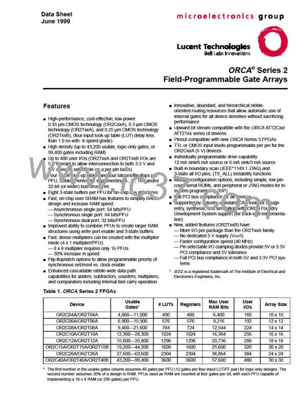
Figure 21. Single PLC View of Inter-PLC Lines
X1 Lines. There are a total of 16 X1 lines per PLC:
eight vertical and eight horizontal. Each of these is sub-
divided into nibble-wide buses: HX1[3:0], HX1[7:4],
VX1[3:0], and VX1[7:4]. An X1 line is one PLC long.
If a net is longer than one PLC, an X1 line can be
lengthened to n times its length by turning on n – 1
CIPs. A signal is routed onto an X1 line via the switch-
ing lines.
Table 5. Inter-PLC Routing Resources
Horizontal
Lines
Vertical
Lines
Distance
Spanned
HX1[3:0]
HX1[7:4]
HX4[3:0]
HX4[7:4]
HXL[3:0]
HXH[3:0]
CKL, CKR
VX1[3:0]
VX1[7:4]
VX4[3:0]
VX4[7:4]
VXL[3:0]
VXH[3:0]
CKT, CKB
One PLC
One PLC
Four PLCs
Four PLCs
PLC Array
1/2 PLC Array
PLC Array
X4 Lines. There are four sets of four X4 lines, for a
total of 16 X4 lines per PLC. They are HX4[3:0],
HX4[7:4], VX4[3:0], and VX4[7:4]. Each set of X4 lines
is twisted each time it passes through a PLC, and one
of the four is broken with a CIP. This allows a signal to
be routed for a length of four cells in any direction on a
single line without additional CIPs. The X4 lines can be
used to route any nets that require minimum delay. A
longer net is routed by connecting two X4 lines
together by a CIP. The X4 lines are accessed via the
switching lines.
Figure 21 shows the inter-PLC routing within one PLC.
Figure 22 provides a global view of inter-PLC routing
resources across multiple PLCs.
Lucent Technologies Inc.
19

 ETC [ ETC ]