Data Sheet
June 1999
ORCA Series 2 FPGAs
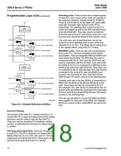
Switching Lines. There are four sets of switching lines
in each PLC, one in each corner. Each set consists of
five switching elements, labeled SUL[4:0], SUR[4:0],
SLL[4:0], and SLR[4:0], for the upper-left, upper-right,
lower-left, and lower-right sections of the PFUs,
Programmable Logic Cells (continued)
TRI
respectively. The switching lines connect to the PFU
inputs and outputs as well as the BIDI and BIDIH lines,
to be described later. They also connect to both the
horizontal and vertical X1 and X4 lines (inter-PLC rout-
ing resources, described below) in their specific corner.
BIDI
CONTROLLER
RIGHT-LEFT BIDI
One of the four sets of switching lines can be con-
nected to a set of switching lines in each of the four
adjacent PLCs or PICs. This allows direct routing of up
to five signals without using inter-PLC routing.
LEFT-RIGHT BIDI
UNUSED BIDI
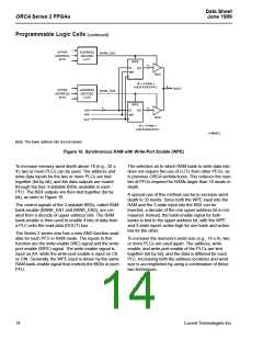
BIDI/BIDIH Lines. There are two sets of bidirectional
lines in the PLC, each set consisting of four bidirec-
tional buffers. They are designated BIDI and BIDIH and
have similar functionality. The BIDI lines are used in
conjunction with the XL lines, and the BIDIH lines are
used in conjunction with the XH lines. Each side of the
four BIDIs in the PLC is connected to a BIDI line on the
left (BL[3:0]) and on the right (BR[3:0]). These lines can
be connected to the XL lines through CIPs, with BL[3:0]
connected to the vertical XL lines and BR[3:0] con-
nected to the horizontal XL lines. Both BL[3:0] and
BR[3:0] have CIPs which connect to the switching lines.
LEFT-RIGHT BIDI
BIDIH
CONTROLLER
RIGHT-LEFT BIDIH
LEFT-RIGHT BIDIH
UNUSED BIDIH
Similarly, each side of the four BIDIHs is connected to a
BIDIH line: BLH[3:0] on the left and BRH[3:0] on the
right. These lines can also be connected to the XH
lines through CIPs, with BLH[3:0] connected to the ver-
tical XH lines and BRH[3:0] connected to the horizontal
XH lines. Both BLH[3:0] and BRH[3:0] have CIPs which
connect to the switching lines.
LEFT-RIGHT BIDIH
CIPs are also provided to connect the BIDIH and BIDIL
lines together on each side of the BIDIs. For example,
BLH3 can connect to BL3, while BRH3 can connect to
BR3.
5-4479p2(F)
Figure 20. 3-Statable Bidirectional Buffers
Intra-PLC Routing
The function of the intra-PLC routing resources is to
connect the PFU’s input and output ports to the routing
resources used for entry to and exit from the PLC.
These are nets for providing PFU feedback, turning
corners, or switching from one type of routing resource
to another.
PFU Input and Output Ports. There are 19 input ports
to each PFU. The PFU input ports are labeled A[4:0],
B[4:0], WD[3:0], C0, CK, LSR, CIN, and CE. The six
output ports are O[4:0] and COUT. These ports corre-
spond to those described in the PFU section.
18
Lucent Technologies Inc.

 ETC [ ETC ]