Proprietary TranSwitch Corporation Information for use Solely by its Customers
L3M
TXC-03452B
DATA SHEET
Performance Counters And Fifo Leak Rate
All 16-bit performance counters allow uninterrupted access, without the danger of one byte changing while the
other byte is read. To perform a 16-bit read, the low order byte is read first. This causes the high order byte of
the counter to be transferred to a common high order byte at location FFH. The common high order byte
should be read next to complete the count transfer; if another performance counter low order byte is read first,
the contents of the common high order byte will change to reflect the performance counter just read. Counts
that occur during the read cycle are held for the counter to be updated afterwards.
All the performance counters can also be configured to be either saturating or non-saturating. When a 1 is writ-
ten to control bit COR (clear on read), the performance counters are configured to be saturating, with the
counters stopping at their maximum count. An 8-bit or 16-bit counter is reset on a microprocessor read cycle.
When a 0 is written to control bit COR, the performance counters are configured to be non-saturating, and roll
over to zero after the maximum count in the counter is reached. The counters are then not cleared on a read
cycle.
All the performance counters can be reset simultaneously by writing a 1 to control bit RESETC. This bit is self
clearing, and does not require writing a 0 into this location.
All drop bus related performance counters are inhibited (i.e., will not increment) when one or more of the fol-
lowing alarms occurs:
- Loss of Drop bus clock (DLOC)
- Loss of Drop bus J1 (DLOJ1)
- AIS detected in the E1 byte (when XALM2AIS = 0)
- When either ISTAT or PAIS lead is high (when XALM2AIS = 1)
- Loss of pointer (TUG-3)
- Path AIS (TUG-3)
The performance counters can also be written by the microprocessor. However, when writing to a 16-bit
counter (at locations n, n+1) it is recommended that the low order byte at location n should be written first. The
high order byte can be written by addressing location n + 1. Since the writes occur in separate cycles, care
must be taken to prevent the low byte from carrying-out to the high byte before the high byte is initialized. Writ-
ing a low byte equal to 00H will provide the maximum time for the microprocessor to update the high byte.
Address
Bit
Symbol
Description
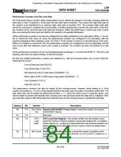
A0
7-0
Rcv Frame Receive SDH/SONET Frame Count: Counts the number of received
Cnt
SDH/SONET frames.
Not used.
A1
A2
7-0
7-0
FIFO
Leak
Rate
FIFO Leak Rate Register: The number written into this location repre-
sents the number of frames between consecutive leaked bits, in multiples
of four frames (i.e., a value of x means that there are 4x frames between bit
leaks). The recommended value of zero causes a bit to be leaked every
other frame.
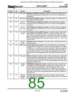
A3
7-0
INC Count Positive Justification Counter: Counts the number of positive (incre-
ment) pointer movements in the AUG/VC-4 or STS-3/STS-1 based on J1
movements.
TXC-03452B-MB
Ed. 6, April 2001
- 84 of 96 -

 ETC [ ETC ]