Proprietary TranSwitch Corporation Information for use Solely by its Customers
L3M
TXC-03452B
DATA SHEET
Address
Bit
Symbol
Description
A4
7-0
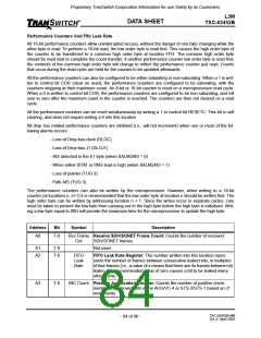
DEC Count Negative Justification Counter: Counts the number of negative (decre-
ment) pointer movements in the AUG/VC-4 or STS-3/STS-1 based on J1
movements.
A5
A6
7-0
7-0
New Count New Data Flag (NDF) Counter: Counts the number of J1 movements for
the AUG/VC-4 or STS-3/STS-1.
TUG-3
TUG-3 Positive Justification Counter: Counts the number of positive
INC Count (increment) pointer movements in the TUG-3, based on interpretation of
H1 and H2.
A7
A8
7-0
7-0
TUG-3
TUG-3 Negative Justification Counter: Counts the number of negative
DEC Count (decrement) pointer movements in the TUG-3, based on interpretation of
H1 and H2.
TUG-3 NDF TUG-3 New Data Flag (NDF) Counter: Counts the number of New Data
Count
Flags (NDFs) or new pointers in the TUG-3 pointer (H1/H2). Note: The
TUG-3 NDF counter will not register a count when the pointer is changed
between certain sets of values (i.e., 192 to 194 or 193 to 195). The TUG-3
NDF counter will register two counts for the inverse case, (i.e., 194 to 192
or 195 to 193).
A9
AA
7-0
7-0
B3 Block B3 Blocks (in error) Counter: Counts the number of B3 blocks which are
Count received in error.
FEBE Count Far End Block Error Counter: Counts the FEBE error count indication
received in bits 1 through 4 of G1 when control bit FEBEBLK is a 0. When
FEBEBLK is a 1, one or more errors per received G1 byte are counted as
1 error (block). Location AAH is the low order byte, while location ABH is
the high order byte of the 16-bit counter. After reading the low order byte
from AAH the corresponding high order byte (ABH) should be read from
FFH.
AC
AE
7-0
7-0
B3 Counter B3 Error Counter: Counts the number of B3 errors that occur between the
incoming value and calculated value. Location ACH is the low order byte,
while location ADH is the high order byte of the 16-bit counter. After read-
ing the low order byte from ACH the corresponding high order byte (ADH)
should be read from FFH.
Coding
Errors
HDB3/B3ZS Coding Error Counter: Counts the number of internal cod-
ing violation errors detected when in P/N rail mode. Location AEH is the
low order byte while location AFH is the high order byte of the 16-bit
counter. When control bit ENANA is set to 1, PRBS errors are counted
when the internal analyzer is in lock (no OOL alarm). After reading the low
order byte from AEH the corresponding high order byte (AFH) should be
read from FFH.
FF
7-0
Common Common High Order Byte: This location contains a copy of the high
High Byte order byte that was associated with the low order byte of the 16-bit counter
Count
most recently read.
TXC-03452B-MB
Ed. 6, April 2001
- 85 of 96 -

 ETC [ ETC ]