Proprietary TranSwitch Corporation Information for use Solely by its Customers
L3M
TXC-03452B
DATA SHEET
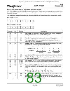
Receive Path Overhead Bytes, Tug-3 H1/h2 Bytes And “O”-bits
The received bytes are written into the locations given below, and are also provided at the receive Path Over-
head byte interface.
The relationship between a received Path Overhead byte and the corresponding RAM location is as follows:
Bits of RAM Location:
7
6
5
4
3
2
1
0
Bits of Received POH Byte:
1
2
3
4
5
6
7
8
Address
Bit
Symbol
Description
50
to
7-0
J1
Path Trace: The received J1 bytes are written in the 64 byte segment in a
rotating fashion. There is no specific starting point.
8F
90
91
7-0
7-0
B3
C2
Path B3: The value in this location is the received B3 parity byte.
Path Signal Label: These bits indicate the construction of the AU-3,
TUG-3, or SPE (e.g., unequipped).
92
7-0
G1
Receive Byte G1: This location provides the receive status of the FEBE
bits, Path RDI, and unassigned bits in the G1 byte.
Receive G1 Bit
RAM Bit
1
7
2
6
3
5
4
4
5
3
6
2
7
1
8
0
RFEBE
RRDI
Unassigned
93
94
7-0
7-0
F2
H4
User Channel: This location provides user information between elements.
H4 Byte: This byte is not specified for use in this application. It is provided
for future use as required.
95
96
97
7-0
7-0
7-0
Z3 (F3)
Z4 (K3)
Z5 (N1)
Path Growth: The Z3, Z4 and Z5 bytes are designated for future growth.
The Z5 byte has been assigned for Tandem Connection application.
98
99
7-0
H1
H2
Received H1 and H2 Pointer: The contents of the H1 and H2 pointer for a
TUG-3 are provided in the following bit order for a microprocessor read
cycle.
H1
H2
Bit 7 6 5 4 3 2 1 0
N N N N S S I D
7 6 5 4 3 2 1 0
I
D I D I D I
D
9A
1
0
RO2
RO1
Receive “O”-Bits: The received states of the two Overhead Communica-
tion channel bits found in the nine subframes in the DS3 format or the
three subframes in the E3 format. The two bits are updated once a frame
from one of the subframes in the frame.
TXC-03452B-MB
Ed. 6, April 2001
- 83 of 96 -

 ETC [ ETC ]