Proprietary TranSwitch Corporation Information for use Solely by its Customers
L3M
TXC-03452B
DATA SHEET
OPERATION
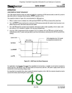
L3M POWER-UP RESET SEQUENCE
The L3M requires that the clocks are valid and stable for a minimum of 200 nanoseconds in order for a reset to
take effect (refer to Hardware Reset function, RESET, lead 86 or K14).
The sequence shown in Figure 30 is recommended on L3M power-up:
1. When a system reset is initiated, the L3M input leads RESET and TRI are set low at the same time.
2. The L3M RESET lead is held low for a minimum of 200 nanoseconds after the system reset has been com-
pleted and all of the L3M clocks have become stable.
3. The L3M TRI lead then remains low to hold the L3M outputs with tri-state capability in the tri-state condi-
tion until the TUG-3 position in register C0H has been programmed.
4. Once the L3M is programmed for the assigned TUG-3 in register C0H, the TRI lead is set high and the
L3M will lock to the C1 pulse and map data to and from the positions selected by the DPOSn and APOSn
settings.
System reset
L3M configuration reg. C0H should
be programmed during this time.
200 ns (Min.)
Sys Reset
L3M RESET
L3M TRI
Figure 30. L3M Power-Up Reset Sequence
For application circuit boards that require the capability for hot insertion, a suitable circuit must be included to
ensure that the L3M RESET and TRI input leads are forced low until the L3M power supply leads have all
reached the normal operating voltage range.
It is important to remember that, when reading the latched registers in the L3M, the contents should be read a
second time before determining the current status.
TXC-03452B-MB
Ed. 6, April 2001
- 49 of 96 -

 ETC [ ETC ]