Proprietary TranSwitch Corporation Information for use Solely by its Customers
L3M
TXC-03452B
DATA SHEET
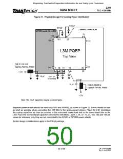
Figure 31. Physical Design For Analog Power Distribution
0.01µF
0.01µF
APWR2 Leads 18,98
73
APWR Leads 10,14,101
108
109
•
•
101
98
72
L3M PQFP
Top View
EMI 25-120 MHz
37
Digi-Key Part No. P9809
144
1 10 14
18
36
•
•
•
+ 5V
♦
•
10 µF
0.01 µF
(3 places)
•
10 µF
EMI 25-120 MHz
Digi-Key Part No. P9809
♦
+ 5V
Note: The 10 µF capacitors may be polarized types.
Separate power islands should be used for APWR and APWR2, as shown in Figure 31. Traces should be kept
as short as possible when connecting the EMI filter to the analog power planes. Place the 0.01 microfarad
decoupling capacitors as close as possible to the associated device lead and on the same board side as the
L3M. Place the 10 microfarad capacitors close to the EMI filters. Leads 1, 36, 37, 72, 73, 108, 109 and 144 are
shown for reference only, they are not connected to the APWR or APWR2 power islands.
Similar design considerations apply to the PBGA package.
TXC-03452B-MB
Ed. 6, April 2001
- 50 of 96 -

 ETC [ ETC ]