APEX 20K Programmable Logic Device Family Data Sheet
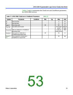
Tables 17 and 18 summarize the ClockLock and ClockBoost parameters
for APEX 20KE devices.
Table 17. APEX 20KE ClockLock & ClockBoost Parameters
Symbol Parameter Condition
Note (1)
Min
Typ
Max
Unit
tR
Input rise time
5
5
ns
ns
%
tF
Input fall time
tINDUTY
tINJITTER
Input duty cycle
40
45
60
Input jitter peak-to-peak
2% of input peak-to-
period
peak
tOUTJITTER Jitter on ClockLock or ClockBoost-
0.35% of
output period
RMS
generated clock
tOUTDUTY
Duty cycle for ClockLock or
ClockBoost-generated clock
55
40
%
tLOCK (2),
(3)
Time required for ClockLock or
ClockBoost to acquire lock
µs
Altera Corporation
53

 ETC [ ETC ]