APEX 20K Programmable Logic Device Family Data Sheet
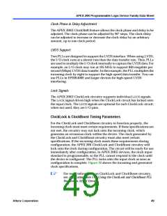
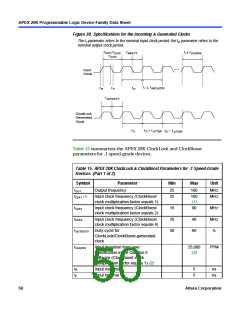
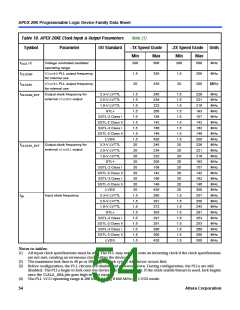
Figure 30. Specifications for the Incoming & Generated Clocks
The t parameter refers to the nominal input clock period; the t parameter refers to the
I
O
nominal output clock period.
+
tI tCLKDEV
f
,
CLK1 fCLK2
,
tINDUTY
fCLK4
Input
Clock
+
tI tINCLKSTB
tR
tF
tO
tOUTDUTY
ClockLock
Generated
Clock
+
tO
tO tJITTER
tO tJITTER
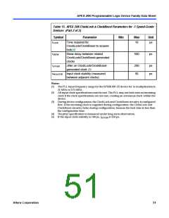
Table 15 summarizes the APEX 20K ClockLock and ClockBoost
parameters for -1 speed-grade devices.
Table 15. APEX 20K ClockLock & ClockBoost Parameters for -1 Speed-Grade
Devices (Part 1 of 2)
Symbol
Parameter
Min
Max
Unit
fOUT
fCLK1 (1)
Output frequency
25
25
180
MHz
MHz
Input clock frequency (ClockBoost
clock multiplication factor equals 1)
180
(1)
fCLK2
Input clock frequency (ClockBoost
clock multiplication factor equals 2)
16
10
40
90
48
60
MHz
MHz
%
fCLK4
Input clock frequency (ClockBoost
clock multiplication factor equals 4)
tOUTDUTY
Duty cycle for
ClockLock/ClockBoost-generated
clock
fCLKDEV
Input deviation from user
25,000
PPM
specification in the Quartus II
software (ClockBoost clock
multiplication factor equals 1) (2)
(3)
tR
tF
Input rise time
Input fall time
5
5
ns
ns
50
Altera Corporation

 ETC [ ETC ]