Si3210/Si3211/Si3212
8 kHz
Clock
8 kHz
Clock
OZn
Zero Cross
OnE
OSSn
to TX Path
Enable
Zero
Cross
Logic
Two-Pole
Resonance
Oscillator
16-Bit
Modulo
Counter
OAT
Expire
Signal
Routing
Register
Load
Load
Logic
OIT
Expire
to RX Path
OSCn
OATn
OITn
OnIP REL*
INT
Logic
OATnE
OITnE
OnSO
OSCnX
OSCnY
OnIE
OnAP
INT
Logic
OnAE
*Tone Generator 1 Only
n = "1" or "2" for Tone Generator 1 and 2, respectively
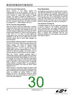
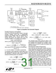
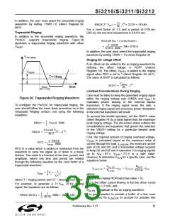
Figure 18. Simplified Tone Generator Diagram
Oscillator Frequency and Amplitude
2π1336
8000
--------------------
coeff2 = cos
= 0.49819
Each of the two tone generators contains a two-pole
resonate oscillator circuit with
a
programmable
15
OSC2 = 0.49819 (2 ) = 16324 = 3FC4h
frequency and amplitude, which are programmed via
indirect registers OSC1, OSC1X, OSC1Y, OSC2,
OSC2X, and OSC2Y. The sample rate for the two
oscillators is 8000 Hz. The equations are as follows:
1
0.50181
--
OSC2X =
--------------------- (215 – 1) 0.5 = 2370 = 942h
4
1.49819
OSC2Y = 0
coeff = cos(2π f /8000 Hz),
n
n
The computed values above would be written to the
corresponding registers to initialize the oscillators. Once
the oscillators are initialized, the oscillator control
registers can be accessed to enable the oscillators and
direct their outputs.
where f is the frequency to be generated;
n
15
OSCn = coeff (2 );
n
Desired VRMS
1
4
--
---------------------------------------
1.11 VRMS
OSCnX =
----------------------- (215 – 1)
1 – coeff
1 + coeff
Tone Generator Cadence Programming
where desired Vrms is the amplitude to be generated;
OSCnY = 0,
Each of the two tone generators contains two timers,
one for setting the active period and one for setting the
inactive period. The oscillator signal is generated during
the active period and suspended during the inactive
period. Both the active and inactive periods can be
programmed from 0 to 8 seconds in 125 µs steps. The
active period time interval is set using OAT1 (direct
registers 36 and 37) for tone generator 1 and OAT2
(direct registers 40 and 41) for tone generator 2.
n = 1 or 2 for oscillator 1 or oscillator 2, respectively.
For example, in order to generate a DTMF digit of 8, the
two required tones are 852 Hz and 1336 Hz. Assuming
the generation of half-scale values (ignoring twist) is
desired, the following values are calculated:
2π852
----------------
coeff1 = cos
= 0.78434
8000
OSC1 = 0.78434(215) = 25701= 6465h
To enable automatic cadence for tone generator 1,
define the OAT1 and OIT1 registers and then set the
O1TAE bit (direct Register 32, bit 4) and O1TIE bit
(direct Register 32, bit 3). This enables each of the
timers to control the state of the Oscillator Enable bit,
O1E (direct Register 32, bit 2). The 16-bit counter will
begin counting until the active timer expires, at which
1
4
0.21556
1.78434
--
OSC1X =
--------------------- (215 – 1) 0.5 = 1424 = 590h
OSC1Y = 0
Preliminary Rev. 1.11
31

 ETC [ ETC ]