Si3210/Si3211/Si3212
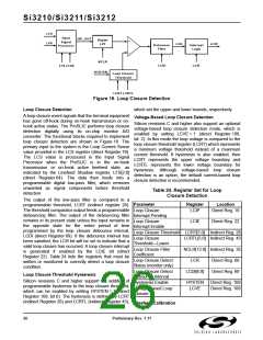
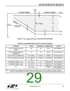
VOC
ILIM
RLOOP
Constant I Region
Constant V Region
VCM
VTIP
VOC
|VTIP - VRING
|
VBATL
TRACK=0
VOV
VRING
VBAT
VOV
V
Figure 17. V , V
, and V
in the Forward Active State
BAT
TIP RING
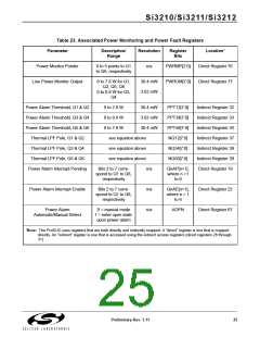
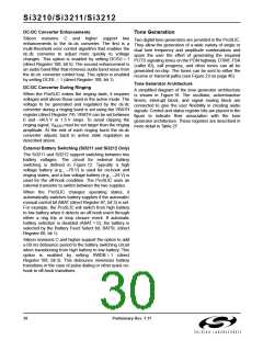
Table 26. Associated Relevant DC-DC Converter Registers
Parameter
Range
Resolution Register Bit
Location
DC-DC Converter Power-off
Control
n/a
n/a
DCOF
Direct Register 14
DC-DC Converter Calibration
Enable/Status
n/a
n/a
DCCAL
Direct Register 93
DC-DC Converter PWM Period
DC-DC Converter Min. Off Time
0 to 15.564 us
61.035 ns
61.035 ns
DCN[7:0]
Direct Register 92
Direct Register 93
(0 to 1.892 us) +
4 ns
DCTOF[4:0]
High Battery Voltage—V
Low Battery Voltage—V
0 to –94.5 V
0 to –94.5 V
1.5 V
1.5 V
1.5 V
VBATH[5:0]
VBATL[5:0]
Direct Register 74
Direct Register 75
BATH
BATL
V
0 to –9 V or
0 to –13.5 V
VMIND[3:0]
VOV
Indirect Register 41
Direct Register 66
OV
Note: The ProSLIC uses registers that are both directly and indirectly mapped. A “direct” register is one that is mapped
directly. An “indirect” register is one that is accessed using the indirect access registers (direct registers 28 through 31).
Preliminary Rev. 1.11
29

 ETC [ ETC ]