Si3210/Si3211/Si3212
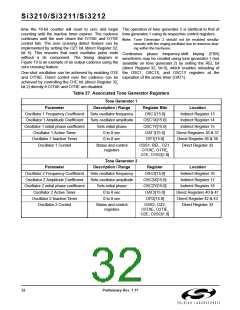
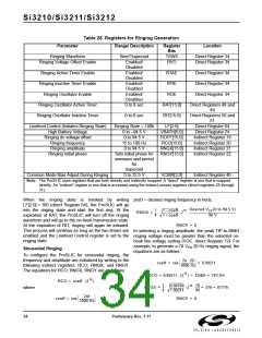
Table 28. Registers for Ringing Generation
Parameter
Range/ Description
Register
Bits
Location
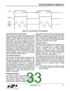
Ringing Waveform
Ringing Voltage Offset Enable
Sine/Trapezoid
Enabled/
Disabled
Enabled/
Disabled
Enabled/
Disabled
Enabled/
Disabled
0 to 8 sec
TSWS
RVO
Direct Register 34
Direct Register 34
Ringing Active Timer Enable
Ringing Inactive Timer Enable
Ringing Oscillator Enable
RTAE
RTIE
Direct Register 34
Direct Register 34
Direct Register 34
ROE
Ringing Oscillator Active Timer
Ringing Oscillator Inactive Timer
RAT[15:0]
RIT[15:0]
Direct Registers 48 and
49
Direct Registers 50 and
51
0 to 8 sec
Linefeed Control (Initiates Ringing State)
High Battery Voltage
Ringing State = 100b
0 to –94.5 V
0 to 94.5 V
15 to 100 Hz
0 to 94.5 V
Sets initial phase for
sinewave and period
for
LF[2:0]
Direct Register 64
Direct Register 74
Indirect Register 19
Indirect Register 20
Indirect Register 21
Indirect Register 22
VBATH[5:0]
ROFF[15:0]
RCO[15:0]
RNGX[15:0]
RNGY[15:0]
Ringing dc voltage offset
Ringing frequency
Ringing amplitude
Ringing initial phase
trapezoid
Common Mode Bias Adjust During Ringing
0 to 22.5 V
VCMR[3:0]
Indirect Register 40
Note: The ProSLIC uses registers that are both directly and indirectly mapped. A “direct” register is one that is mapped
directly. An “indirect” register is one that is accessed using the indirect access registers (direct registers 28 through
31).
When the ringing state is invoked by writing and f = desired ringing frequency in hertz.
LF[2:0] = 100 (direct Register 64), the ProSLIC will go
Desired VPK(0 to 94.5 V)
-----------------------------------------------------------------------
96 V
into the ringing state and start the first ring. At the
expiration of RAT, the ProSLIC will turn off the ringing
waveform and will go to the on-hook transmission state.
At the expiration of RIT, ringing will again be initiated.
This process will continue as long as the two timers are
enabled and the Linefeed Control register is set to the
ringing state.
1
4
15
1 – coeff
1 + coeff
--
RNGX =
----------------------- 2
RNGY = 0
In selecting a ringing amplitude, the peak TIP-to-RING
ringing voltage must be greater than the selected on-
hook line voltage setting (VOC, direct Register 72). For
example, to generate a 70 V 20 Hz ringing signal, the
equations are as follows:
PK
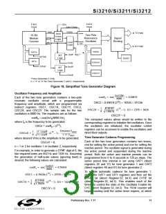
Sinusoidal Ringing
To configure the ProSLIC for sinusoidal ringing, the
frequency and amplitude are initialized by writing to the
following indirect registers: RCO, RNGX, and RNGY.
The equations for RCO, RNGX, RNGY are as follows:
2π 20
1000 Hz
----------------------
coeff = cos
= 0.99211
RCO = 0.99211 (215) = 32509 = 7EFDh
RCO = coeff (215
)
1
4
15 70
0.00789
1.99211
--
------
= 376 = 0177h
RNGX =
--------------------- 2
where
96
2πf
----------------------
coeff = cos
RNGY = 0
1000 Hz
34
Preliminary Rev. 1.11

 ETC [ ETC ]