Si3210/Si3211/Si3212
In addition, the user must select the sinusoidal ringing
waveform by writing TSWS = 0 (direct Register 34,
bit 0).
71
96
215= 24235 = 5EABh
------
RNGX(71 VPK) =
For a crest factor of 1.3 and a period of 0.05 sec
(20 Hz), the rise time requirement is 0.0153 sec.
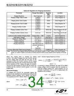
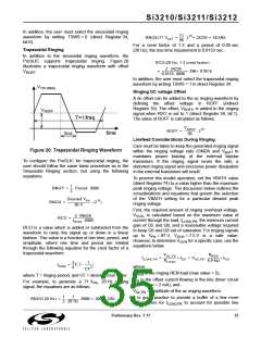
Trapezoidal Ringing
In addition to the sinusoidal ringing waveform, the
ProSLIC supports trapezoidal ringing. Figure 20
illustrates a trapezoidal ringing waveform with offset
RCO(20 Hz, 1.3 crest factor)
2 24235
-----------------------------------
=
= 396= 018Ch
V
.
ROFF
0.0153 8000
In addition, the user must select the trapezoidal ringing
waveform by writing TSWS = 1 in direct Register 34.
VTIP-RING
Ringing DC voltage Offset
A dc offset can be added to the ac ringing waveform by
defining the offset voltage in ROFF (indirect
Register 19). The offset, V
signal when RVO is set to 1 (direct Register 34, bit 1).
The value of ROFF is calculated as follows:
, is added to the ringing
ROFF
VROFF
T=1/freq
VROFF
ROFF =
215
-----------------
tRISE
time
96
Linefeed Considerations During Ringing
Care must be taken to keep the generated ringing signal
Figure 20. Trapezoidal Ringing Waveform
within the ringing voltage rails (GNDA and V
) to
BAT
maintains proper biasing of the external bipolar
transistors. If the ringing signal nears the rails, a
distorted ringing signal and excessive power dissipation
in the external transistors will result.
To configure the ProSLIC for trapezoidal ringing, the
user should follow the same basic procedure as in the
Sinusoidal Ringing section, but using the following
equations:
To prevent this invalid operation, set the VBATH value
(direct Register 74) to a value higher than the maximum
peak ringing voltage. The discussion below outlines the
considerations and equations that govern the selection
of the VBATH setting for a particular desired peak
ringing voltage.
1
2
--
RNGY =
Period 8000
Desired VPK
-----------------------------------
96 V
RNGX =
(215
)
First, the required amount of ringing overhead voltage,
V
, is calculated based on the maximum value of
2 RNGX
tRISE 8000
OVR
-------------------------------
RCO =
current through the load, I
, the minimum current
LOAD,PK
gain of Q5 and Q6, and a reasonable voltage required
to keep Q5 and Q6 out of saturation. For ringing signals
RCO is a value which is added or subtracted from the
waveform to ramp the signal up or down in a linear
fashion. This value is a function of rise time, period, and
amplitude, where rise time and period are related
through the following equation for the crest factor of a
trapezoidal waveform.
up to V = 87 V, V
= 7.5 V is a safe value.
PK
OVR
However, to determine V
for a specific case, use the
OVR
equations below.
VAC,PK
NREN
-------------------
-----------------
+ IOS
ILOAD,PK
=
+ IOS = VAC,PK
RLOAD
6.9 kΩ
3
4
1
CF2
--
----------
tRISE
=
T 1 –
where:
is the ringing REN load (max value = 5),
N
REN
where T = ringing period, and CF = desired crest factor.
I
is the offset current flowing in the line driver circuit
OS
For example, to generate a 71 V , 20 Hz ringing
PK
(max value = 2 mA), and
signal, the equations are as follows:
V
= amplitude of the ac ringing waveform.
AC,PK
1
1
It is good practice to provide a buffer of a few more
-- ---------------
RNGY(20 Hz) =
8000 = 200 = C8h
2 20 Hz
milliamperes for I
to account for possible line
LOAD,PK
Preliminary Rev. 1.11
35

 ETC [ ETC ]