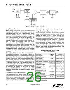
Si3210/Si3211/Si3212
DC-DC Converter Enhancements
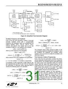
Tone Generation
Silicon revisions
C
and higher support two
Two digital tone generators are provided in the ProSLIC.
They allow the generation of a wide variety of single or
dual tone frequency and amplitude combinations and
spare the user the effort of generating the required
POTS signaling tones on the PCM highway. DTMF, FSK
(caller ID), call progress, and other tones can all be
generated on-chip. The tones can be sent to either the
receive or transmit paths (see Figure 23 on page 40).
enhancements to the dc-dc converter. The first is a
multi-threshold error control algorithm that enables the
dc-dc converter to adjust more quickly to voltage
changes. This option is enabled by setting DCSU = 1
(direct Register 108, bit 5). The second enhancement is
an audio band filter that removes audio band noise from
the dc-dc converter control loop. This option is enabled
by setting DCFIL = 1 (direct Register 108, bit 1).
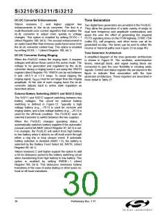
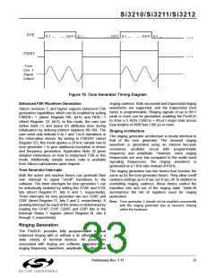
Tone Generator Architecture
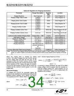
DC-DC Converter During Ringing
A simplified diagram of the tone generator architecture
is shown in Figure 18. The oscillator, active/inactive
timers, interrupt block, and signal routing block are
connected to give the user flexibility in creating audio
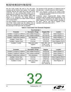
signals. Control and status register bits are placed in the
figure to indicate their association with the tone
generator architecture. These registers are described in
more detail in Table 27.
When the ProSLIC enters the ringing state, it requires
voltages well above those used in the active mode. The
voltage to be generated and regulated by the dc-dc
converter during a ringing burst is set using the VBATH
register (direct Register 74). VBATH can be set between
0 and –94.5 V in 1.5 V steps. To avoid clipping the
ringing signal, V
must be set larger than the ringing
BATH
amplitude. At the end of each ringing burst the dc-dc
converter adjusts back to active state regulation as
described above.
External Battery Switching (Si3211 and Si3212 Only)
The Si3211 and Si3212 support switching between two
battery voltages. The circuit for external battery
switching is defined in Figure 12. Typically a high
voltage battery (e.g., –70 V) is used for on-hook and
ringing states, and a low voltage battery (e.g., –24 V) is
used for the off-hook condition. The ProSLIC uses an
external transistor to switch between the two supplies.
When the ProSLIC changes operating states, it
automatically switches battery supplies if the automatic/
manual control bit ABAT (direct Register 67, bit 3) is set.
For example, the ProSLIC will switch from high battery
to low battery when it detects an off-hook event through
either a ring trip or loop closure event. If automatic
battery selection is disabled (ABAT = 0), the battery is
selected by the Battery Feed Select bit, BATSL (direct
Register 66, bit 1).
Silicon revisions C and higher support the option to add
a 60 ms debounce period to the battery switching circuit
when transitioning from high battery to low battery. This
option is enabled by setting SWDB = 1 (direct
Register 108, bit 3). This debounce minimizes battery
transitions in the case of pulse dialing or other quick on-
hook to off-hook transitions.
30
Preliminary Rev. 1.11

 ETC [ ETC ]