Si3210/Si3211/Si3212
O1E
0,1 ...
..., OAT1 0,1 ...
..., OIT1 0,1 ...
..., OAT1 0,1 ...
...
...
OSS1
Tone
Gen. 1
Signal
Output
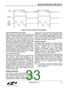
Figure 19. Tone Generator Timing Diagram
Enhanced FSK Waveform Generation
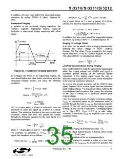
ringing cadence. Both sinusoidal and trapezoidal ringing
waveforms are supported, and the trapezoidal crest
factor is programmable. Ringing signals of up to 88 V
peak or more can be generated, enabling the ProSLIC
to drive a 5 REN (1380 Ω + 40 µF) ringer load across
loop lengths of 2000 feet (160 Ω) or more.
Silicon revisions C and higher support enhanced FSK
generation capabilities, which can be enabled by setting
FSKEN = 1 (direct Register 108, bit 6) and REN = 1
(direct Register 32, bit 6). In this mode, the user can
define mark (1) and space (0) attributes once during
initialization by defining indirect registers 99–104. The
user need only indicate 0-to-1 and 1-to-0 transitions in
the information stream. By writing to FSKDAT (direct
Register 52), this mode applies a 24 kHz sample rate to
tone generator 1 to give additional resolution to timers
and frequency generation. Application Note 32 gives
detailed instructions on how to implement FSK in this
mode. Additionally, sample source code is available
from Silicon Laboratories upon request.
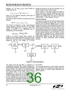
Ringing Architecture
The ringing generator architecture is nearly identical to
that of the tone generator. The sinusoid ringing
waveform is generated using an internal two-pole
resonance oscillator circuit with programmable
frequency and amplitude. However, since ringing
frequencies are very low compared to the audio band
signaling frequencies, the ringing waveform is
generated at a 1 kHz rate instead of 8 kHz.
Tone Generator Interrupts
The ringing generator has two timers that function the
Both the active and inactive timers can generate their same as for the tone generator timers. They allow on/off
own interrupt to signal “on/off” transitions to the cadence settings up to 8 sec on/ 8 sec off. In addition to
software. The timer interrupts for tone generator 1 can controlling ringing cadence, these timers control the
be individually enabled by setting the O1AE and O1IE transition into and out of the ringing state. Table 28
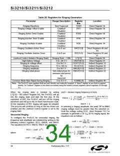
bits (direct Register 21, bits 0 and 1, respectively). summarizes the list of registers used for ringing
Timer interrupts for tone generator two are O2AE and generation.
O2IE (direct Register 21, bits 2 and 3, respectively). A
pending interrupt for each of the timers is determined by
reading the O1AP, O1IP, O2AP, and O2IP bits in the
Interrupt Status 1 register (direct Register 18, bits 0
through 3, respectively).
Note: Tone generator 2 should not be enabled concurrently
with the ringing generator due to resource sharing
within the hardware.
Ringing Generation
The ProSLIC provides fully programmable internal
balanced ringing with or without a dc offset to ring a
wide variety of terminal devices. All parameters
associated with ringing are software programmable:
ringing frequency, waveform, amplitude, dc offset, and
Preliminary Rev. 1.11
33

 ETC [ ETC ]