Si3210/Si3211/Si3212
LCS
Input
Signal
Processor
ISP_OUT
Digital
+
–
LVS
LCR
LCIP
LPF
Debounce
Filter
Interrupt
Logic
NCLR
LCDI
LCIE
LFS LCVE
HYSTEN
Loop Closure
Threshold
LCRT LCRTL
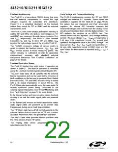
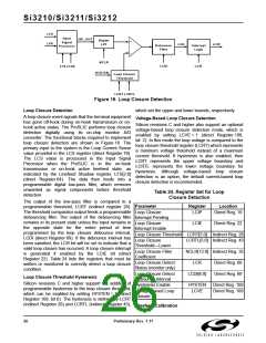
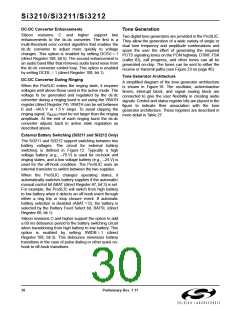
Figure 16. Loop Closure Detection
Loop Closure Detection
which set the upper and lower bounds, respectively.
A loop closure event signals that the terminal equipment
has gone off-hook during on-hook transmission or on-
hook active states. The ProSLIC performs loop closure
detection digitally using its on-chip monitor A/D
converter. The functional blocks required to implement
loop closure detection are shown in Figure 16. The
primary input to the system is the Loop Current Sense
value provided in the LCS register (direct Register 79).
The LCS value is processed in the Input Signal
Processor when the ProSLIC is in the on-hook
transmission or on-hook active linefeed state, as
indicated by the Linefeed Shadow register, LFS[2:0]
(direct Register 64). The data then feeds into a
programmable digital low-pass filter, which removes
unwanted ac signal components before threshold
detection.
Voltage-Based Loop Closure Detection
Silicon revisions C and higher also support an optional
voltage-based loop closure detection mode, which is
enabled by setting LCVE = 1 (direct Register 108,
bit 2). In this mode the loop voltage is compared to the
loop closure threshold register (LCRT) which represents
a minimum voltage threshold instead of a maximum
current threshold. If hysteresis is also enabled, then
LCRT represents the upper voltage boundary and
LCRTL represents the lower voltage boundary for
hysteresis. Although voltage-based loop closure
detection is an option, the default current-based loop
closure detection is recommended.
Table 24. Register Set for Loop
Closure Detection
The output of the low-pass filter is compared to a
programmable threshold, LCRT (indirect register 28).
The threshold comparator output feeds a programmable
debouncing filter. The output of the debouncing filter
remains in its present state unless the input remains in
the opposite state for the entire period of time
programmed by the loop closure debounce interval,
LCDI (direct Register 69). If the debounce interval has
been satisfied, the LCR bit will be set to indicate that a
valid loop closure has occurred. A loop closure interrupt
is generated if enabled by the LCIE bit (direct
Register 22). Table 24 lists the registers that must be
written or monitored to correctly detect a loop closure
condition.
Parameter
Register
Location
Loop Closure
Interrupt Pending
LCIP
Direct Reg. 19
Loop Closure
Interrupt Enable
LCIE
Direct Reg. 22
Loop Closure Threshold LCRT[5:0] Indirect Reg. 28
Loop Closure
Threshold—Lower
LCRTL[5:0] Indirect Reg. 43
Loop Closure Filter
Coefficient
NCLR[12:0] Indirect Reg. 35
Loop Closure Detect
Status (monitor only)
LCR
Direct Reg. 68
Direct Reg. 69
Loop Closure Detect
Debounce Interval
LCDI[6:0]
Loop Closure Threshold Hysteresis
Silicon revisions C and higher support the addition of
programmable hysteresis to the loop closure threshold,
which can be enabled by setting HYSTEN = 1 (direct
Register 108, bit 0). The hysteresis is defined by LCRT
(indirect Register 28) and LCRTL (indirect Register 43),
Hysteresis Enable
HYSTEN
LCVE
Direct Reg. 108
Direct Reg. 108
Voltage-Based Loop
Closure
Linefeed Calibration
26
Preliminary Rev. 1.11

 ETC [ ETC ]