Si3210/Si3211/Si3212
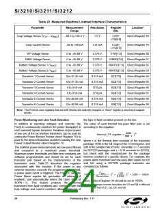
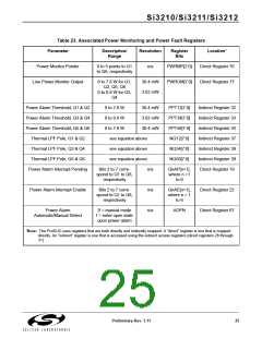
Table 23. Associated Power Monitoring and Power Fault Registers
Parameter
Description/
Range
Resolution
Register
Bits
Location*
Power Monitor Pointer
Line Power Monitor Output
0 to 5 points to Q1
to Q6, respectively
n/a
PWRMP[2:0]
PWROM[7:0]
Direct Register 76
Direct Register 77
0 to 7.8 W for Q1,
Q2, Q5, Q6
0 to 0.9 W for Q3,
Q4
30.4 mW
3.62 mW
Power Alarm Threshold, Q1 & Q2
Power Alarm Threshold, Q3 & Q4
Power Alarm Threshold, Q5 & Q6
Thermal LPF Pole, Q1 & Q2
Thermal LPF Pole, Q3 & Q4
Thermal LPF Pole, Q5 & Q6
Power Alarm Interrupt Pending
0 to 7.8 W
0 to 0.9 W
0 to 7.8 W
30.4 mW
3.62 mW
30.4 mW
PPT12[7:0]
PPT34[7:0]
PPT56[7:0]
NQ12[7:0]
NQ34[7:0]
NQ56[7:0]
Indirect Register 32
Indirect Register 33
Indirect Register 34
Indirect Register 37
Indirect Register 38
Indirect Register 39
Direct Register 19
see equation above
see equation above
see equation above
Bits 2 to 7 corre-
spond to Q1 to Q6,
respectively
n/a
n/a
n/a
QnAP[n+1],
where n =1
to 6
Power Alarm Interrupt Enable
Bits 2 to 7 corre-
spond to Q1 to Q6,
respectively
QnAE[n+1],
where n = 1
to 6
Direct Register 22
Direct Register 67
Power Alarm
Automatic/Manual Detect
0 = manual mode
1 = enter open state
upon power alarm
AOPN
*Note: The ProSLIC uses registers that are both directly and indirectly mapped. A “direct” register is one that is mapped
directly. An “indirect” register is one that is accessed using the indirect access registers (direct registers 28 through
31).
Preliminary Rev. 1.11
25

 ETC [ ETC ]