Si3210/Si3211/Si3212
VCC
GND
R1
200k
38
37
SCLK
SDI
15
20
GND
STIPDC
STIPAC
SPI Bus
36
1
SDO
CS
R8
470
C3
220nF
6
3
4
FSYNC
PCLK
DRX
Q1
5401
Q4
5401
28
29
17
ITIPP
ITIPN
STIPE
R10
10
PCM Bus
Q6
5551
TIP
VCC
5
DTX
C8
220nF
R13
5.1k
C5
R2
200k
R322
10k
22nF
Protection
Circuit
R6
80.6
C6
22nF
26
25
19
2
7
IRINGP
IRINGN
SRINGE
INT
Note 2
Q2
5401
Q3
5401
RESET
RING
R11
10
R4
200k
R262
24
22
40.2k
Q5
5551
IGMP
IGMN
R15
243
C7
220nF
R12
5.1k
R5
200k
18
SVBAT
11
12
14
IREF
CAPP
CAPM
R7
80.6
C4
220nF
R9
470
C2
10uF
C1
10uF
R14
40.2k
21
16
SRINGAC
SRINGDC
Notes:
1. Values and configurations for these
components can be derived from Table 19
or from App Note 45.
13
QGND
R3
200k
C26
0.1uF
GND
R21
15
2. Only one component per system needed.
Q9
2N2222
3. All circuit grounds should have a single-
point connection to the ground plane.
VCC
VDDA1
VDDA2
VDDD
VDC
R291
R281
C15
0.1uF
C16
0.1uF
C17
0.1uF
C30
10uF
Note 1
DC-DC Converter
Circuit
VBAT
VDC
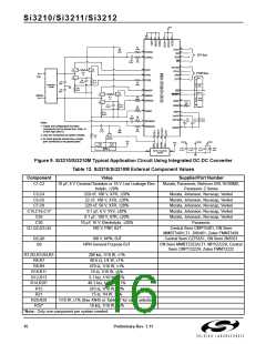
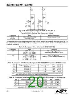
Figure 9. Si3210/Si3210M Typical Application Circuit Using Integrated DC-DC Converter
Table 12. Si3210/Si3210M External Component Values
Component
Value
Supplier/Part Number
C1,C2
10 µF, 6 V Ceramic/Tantalum or 16 V Low Leakage Elec-
trolytic, ±20%
Murata, Panasonic, Nichicon URL16100MD,
Panasonic Z Series
C3,C4
C5,C6
220 nF, 100 V, X7R, ±20%
22 nF, 100 V, X7R, ±20%
220 nF, 50 V, X7R, ±20%
0.1 µF, 6 V, Y5V, ±20%
0.1 µF, 100 V, X7R, ±20%
10 µF, 16 V, Electrolytic, ±20%
100 V, PNP, BJT
Murata, Johanson, Novacap, Venkel
Murata, Johanson, Novacap, Venkel
Murata, Johanson, Novacap, Venkel
Murata, Johanson, Novacap, Venkel
Murata, Johanson, Novacap, Venkel
Panasonic
C7,C8
C15,C16,C17
C26
C30
Q1,Q2,Q3,Q4
Central Semi CMPT5401; ON Semi
MMBT5401LT1, 2N5401; Zetex FMMT5401
Q5,Q6
Q9
100 V, NPN, BJT
Central Semi CZT5551, ON Semi 2N5551
NPN General Purpose BJT
ON Semi MMBT2222ALT1, MPS2222A; Central
Semi CMPT2222A; Zetex FMMT2222
R1,R2,R3,R4,R5
R6,R7
200 kΩ, 1/10 W, ±1%
80.6 Ω, 1/4 W, ±1%
R8,R9
470 Ω, 1/10 W, ±1%
R10,R11
R12,R13
R14,R26*
R15
10 Ω, 1/10 W, ±5%
5.1 kΩ, 1/10 W, ±5%
40.2 kΩ, 1/10 W, ±1%
243 Ω, 1/10 W, ±1%
R21
15 Ω, 1/4 W, ±1%
R28,R29
R32*
1/10 W, ±1% (See AN45 or Table 17 for value selection)
10 kΩ, 1/10 W, ±5%
*Note: Only one component per system needed.
16
Preliminary Rev. 1.11

 ETC [ ETC ]