Si3210/Si3211/Si3212
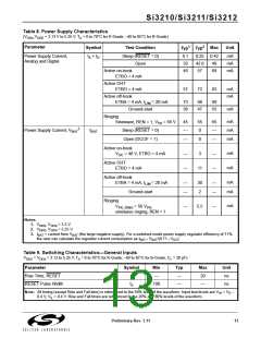
Table 8. Power Supply Characteristics
(V
,V
= 3.13 V to 5.25 V, T = 0 to 70°C for K-Grade, –40 to 85°C for B-Grade)
DDA DDD A
1
2
Parameter
Symbol
I + I
Test Condition
Max
Unit
Typ
Typ
Power Supply Current,
Analog and Digital
Sleep (RESET = 0)
Open
0.1
33
46
0.25 0.42
mA
mA
mA
A
D
42.8
57
49
68
Active on-hook
ETBO = 4 mA
Active OHT
ETBO = 4 mA
Active off-hook
ETBA = 4 mA, I
57
72
83
mA
mA
= 20 mA
73
36
88
47
99
55
LIM
Ground-start
mA
Ringing
mA
mA
mA
Sinewave, REN = 1, V = 56 V
45
—
55
0
65
—
PK
3
Power Supply Current, V
I
Sleep (RESET = 0)
Open (DCOF = 1)
BAT
BAT
—
—
—
0
—
—
—
Active on-hook
mA
mA
V
= 48 V, ETBO = 4 mA
3
OC
Active OHT
ETBO = 4 mA
11
Active off-hook
ETBA = 4 mA, I
mA
mA
= 20 mA
—
—
30
2
—
—
LIM
Ground-start
Ringing
V
mA
= 56 V
,
PK
—
5.5
—
PK_RING
sinewave ringing, REN = 1
Notes:
1. V
2. V
, V
, V
= 3.3 V.
= 5.25 V.
DDD
DDD
DDA
DDA
3. I
= current from V
(the large negative supply). For a switched-mode power supply regulator efficiency of 71%,
BAT
BAT
the user can calculate the regulator current consumption as I
V
/(0.71
V
).
DC
BAT
BAT
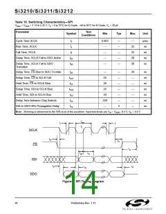
Table 9. Switching Characteristics—General Inputs
V
= V
= 3.13 to 5.25 V, T = 0 to 70°C for K-Grade, –40 to 85°C for B-Grade, C = 20 pF)
DDA
DDA A L
Parameter
Symbol
Min
—
Typ
—
Max
20
Unit
ns
Rise Time, RESET
RESET Pulse Width
t
r
t
100
—
—
ns
rl
Note: All timing (except Rise and Fall time) is referenced to the 50% level of the waveform. Input test levels are V = V
–
D
IH
0.4 V, V = 0.4 V. Rise and Fall times are referenced to the 20% and 80% levels of the waveform.
IL
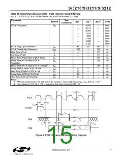
Preliminary Rev. 1.11
13

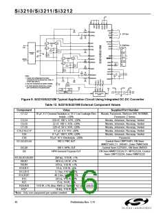
 ETC [ ETC ]