Si3210/Si3211/Si3212
VDC
F1
SDCH
SDCL
R191
C252
10uF
C142
0.1uF
R181
Note 1
R201
C10
22nF
R16
200
Q8
FZT953
DCFF
Q8
D1
ES1D
2N2222
VBAT
C9
10uF
R17
L1
DCDRV
Note 1
GND
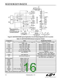
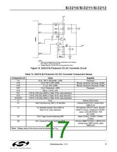
Notes:
1. Values and configurations for these components can be derived
from Table 21 or from App Note 45.
2. Voltage rating for C14 and C25 must be greater than VDC.
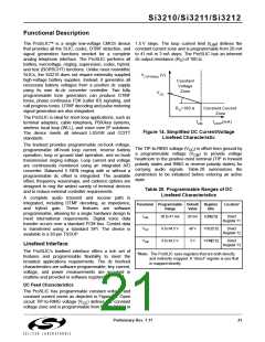
Figure 10. Si3210 BJT/Inductor DC-DC Converter Circuit
Table 13. Si3210 BJT/Inductor DC-DC Converter Component Values
Component (s)
Value
10 µF, 100 V, Electrolytic, ±20%
22 nF, 50 V, X7R, ±20%
Supplier
C9
C10
Panasonic
Murata, Johanson, Novacap, Venkel
Murata, Johanson, Novacap, Venkel
Panasonic
C14*
C25*
R16
0.1 µF, X7R, ±20%
10 µF, Electrolytic, ±20%
200 Ω, 1/10 W, ±5%
R17
1/10 W, ±5% (See AN45 or Table 19 for value selection)
1/4 W, ±5% (See AN45 or Table 19 for value selection)
1/10 W, ±1% (See AN45 or Table 19 for value selection)
Fuse
R18
R19,R20
F1
Belfuse SSQ Series
D1
Ultra Fast Recovery 200 V, 1A Rectifier
General Semi ES1D; Central Semi
CMR1U-02
L1
1A, Shielded Inductor (See AN45 or
Table 19 for value selection)
API Delevan SPD127 series, Sumida
CDRH127 series, Datatronics DR340-1
series, Coilcraft DS5022, TDK
SLF12565
Q7
Q8
120 V, High Current Switching PNP
60 V, General Purpose Switching NPN
Zetex FZT953, FZT955, ZTX953,
ZTX955
ON Semi MMBT2222ALT1, MPS2222A;
Central Semi CMPT2222A; Zetex
FMMT2222
*Note: Voltage rating of this device must be greater than V
.
DC
Preliminary Rev. 1.11
17

 ETC [ ETC ]