<ꢀ5ꢁꢀꢂꢃ<ꢀ.ꢁꢀꢂ
'PJCPEGFꢄ<ꢁꢀꢂꢄ/KETQRTQEGUUQT
ZiLOG
6&4'ꢅꢄ6TCPUOKVꢄ&CVCꢄ4GIKUVGTꢄ'ORV[ꢄꢌ$KVꢄꢁꢍꢆꢄ6&4'ꢅ ꢐ
1 indicates that the 6&4 is empty and the next transmit data
byte is written to 6&4. After the byte is written to 6&4,
6&4' is cleared toꢅ0until the ASCI transfers the byte from
6&4 to the 654 and then 6&4' is again set to 1. 6&4' is
set to 1 in +15612 mode and during 4'5'6. On ASCI0,
if the %65ꢀ pin is auto-enabled in the #5':6ꢀ register and
the pin is High, 6&4' is reset to 0.
#5%+ꢀ requests an interrupt when &%&ꢀ goes High. 4+' is
cleared toꢅ0by 4'5'6.
&%&ꢂꢅꢄ&CVCꢄ%CTTKGTꢄ&GVGEVꢄꢌ$KVꢄꢇꢄ56#6ꢂꢍꢆꢄThis bit is set
to 1 when the pin is High. It is cleared toꢅ0on the first
4'#& of 56#6ꢀ following the pin’s transition from High
to Low and during 4'5'6. When bit 6 of the #5':6ꢀ reg-
ister isꢅ0 to select auto-enabling, and the pin is negated
(High), the receiver is reset and its operation is inhibited.
6+'ꢅꢄ6TCPUOKVꢄ+PVGTTWRVꢄ'PCDNGꢄꢌ$KVꢄꢂꢍꢆꢄ6+' should be set
to 1 to enable ASCI transmit interrupt requests. If 6+'ꢅꢐ
1, an interrupt is requested when 6&4'ꢅꢐ 1. 6+' is cleared
toꢅ0during 4'5'6.
%65ꢁ'ꢅꢄ%NGCTꢄ6Qꢄ5GPFꢄꢌ$KVꢄꢇꢄ56#6ꢁꢍꢆꢄChannel 1 fea-
tures an external %65ꢄ input, which is multiplexed with the
receive data pin 45: for the CSI/O. Setting this bit to 1
selects the %65ꢄ function; clearing the bit toꢅ0selects the
4:5 function.
#5%+ꢄ64#05/+6ꢄ#ꢄ4')+56'45
Register addresses 06H and 07H hold the ASCI transmit
data for channel 0 and channel 1, respectively.
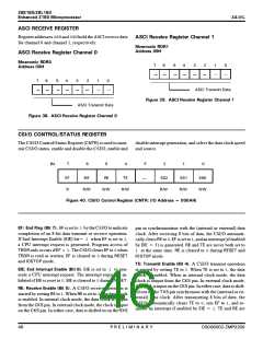
#5%+ꢄ6TCPUOKVꢄ&CVCꢄ4GIKUVGTUꢄ%JCPPGNꢄꢁ
/PGOQPKEꢄ6&4ꢁ
#FFTGUUꢄꢂꢐ*
#5%+ꢄ6TCPUOKVꢄ&CVCꢄ4GIKUVGTUꢄ%JCPPGNꢄꢂ
ꢂ
ꢊ
ꢁ
ꢏ
ꢎ
ꢍ
ꢄ
ꢀ
/PGOQPKEꢄ6&4ꢂ
#FFTGUUꢄꢂꢈ*
ꢂ
ꢊ
ꢁ
ꢏ
ꢎ
ꢍ
ꢄ
ꢀ
#5%+ꢅ6TCPUOKV
ꢅ%JCPPGNꢅꢄ
(KIWTG ꢋꢐꢆ #5%+ꢄ4GIKUVGT
#5%+ꢅ6TCPUOKV
ꢅ%JCPPGNꢅꢀ
(KIWTG ꢋꢈꢆ #5%+ꢄ4GIKUVGT
&5ꢀꢀꢁꢀꢀꢂꢃ</2ꢀꢂꢀꢀ
2ꢅ4ꢅ'ꢅ.ꢅ+ꢅ/ꢅ+ꢅ0ꢅ#ꢅ4ꢅ;
ꢎꢏ

 ZILOG [ ZILOG, INC. ]