eZ80L92 MCU
Product Specification
173
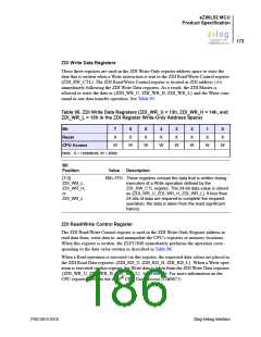
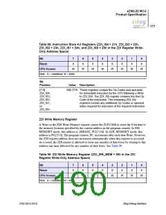
ZDI Write Data Registers
These three registers are used in the ZDI Write-Only register address space to store the
data that is written when a Write instruction is sent to the ZDI Read/Write Control register
(ZDI_RW_CTL). The ZDI Read/Write Control register is located at ZDI address 16h
immediately following the ZDI Write Data registers. As a result, the ZDI Master is
allowed to write the data to {ZDI_WR_U, ZDI_WR_H, ZDI_WR_L} and the Write com-
mand in one data transfer operation. See Table 95.
Table 95. ZDI Write Data Registers (ZDI_WR_U = 13h, ZDI_WR_H = 14h, and
ZDI_WR_L = 15h in the ZDI Register Write-Only Address Space)
Bit
7
X
6
X
5
X
4
X
3
X
2
X
1
X
0
X
Reset
CPU Access
W
W
W
W
W
W
W
W
Note: X = Undefined; W = Write.
Bit
Position
Value
Description
[7:0]
00h–FFh These registers contain the data that is written during
execution of a Write operation defined by the
ZDI_RW_CTL register. The 24-bit data value is stored
as {ZDI_WR_U, ZDI_WR_H, ZDI_WR_L}. If less than
24 bits of data are required to complete the required
operation, the data is taken from the least significant
byte(s).
ZDI_WR_L,
ZDI_WR_H,
or
ZDI_WR_L
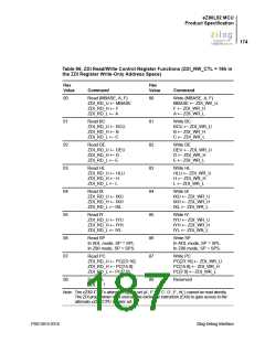
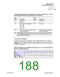
ZDI Read/Write Control Register
The ZDI Read/Write Control register is used in the ZDI Write-Only Register address to
read data from, write data to, and manipulate the CPU’s registers or memory locations.
When this register is written, the ZLP12840 immediately performs the operation corre-
sponding to the data value written as described in Table 96.
When a Read operation is executed via this register, the requested data values are placed in
the ZDI Read Data registers {ZDI_RD_U, ZDI_RD_H, ZDI_RD_L}. When a Write oper-
ation is executed via this register, the Write data is taken from the ZDI Write Data registers
{ZDI_WR_U, ZDI_WR_H, ZDI_WR_L}. See Table 96. For more information on the
CPU registers, refer to the eZ80® CPU User Manual (UM0077).
PS013015-0316
Zilog Debug Interface

 ZILOG [ ZILOG, INC. ]