eZ80L92 MCU
Product Specification
170
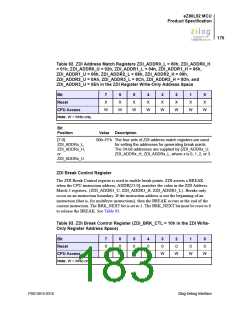
Table 92. ZDI Address Match Registers ZDI_ADDR0_L = 00h, ZDI_ADDR0_H
= 01h, ZDI_ADDR0_U = 02h, ZDI_ADDR1_L = 04h, ZDI_ADDR1_H = 05h,
ZDI_ADDR1_U = 06h, ZDI_ADDR2_L = 08h, ZDI_ADDR2_H = 09h,
ZDI_ADDR2_U = 0Ah, ZDI_ADDR3_L = 0Ch, ZDI_ADDR3_H = 0Dh, and
ZDI_ADDR3_U = 0Eh in the ZDI Register Write-Only Address Space
Bit
7
X
6
X
5
X
4
X
3
X
2
X
1
X
0
X
Reset
CPU Access
Note: W = Write-only.
W
W
W
W
W
W
W
W
Bit
Position
Value Description
[7:0]
00h–FFh The four sets of ZDI address match registers are used
for setting the addresses for generating break points.
The 24-bit addresses are supplied by {ZDI_ADDRx_U,
ZDI_ADDRx_H, ZDI_ADDRx_L, where x is 0, 1, 2, or 3.
ZDI_ADDRx_L,
ZDI_ADDRx_H,
or
ZDI_ADDRx_U
ZDI Break Control Register
The ZDI Break Control register is used to enable break points. ZDI asserts a BREAK
when the CPU instruction address, ADDR[23:0], matches the value in the ZDI Address
Match 3 registers, {ZDI_ADDR3_U, ZDI_ADDR3_H, ZDI_ADDR3_L}. Breaks only
occur on an instruction boundary. If the instruction address is not the beginning of an
instruction (that is, for multibyte instructions), then the BREAK occurs at the end of the
current instruction. The BRK_NEXT bit is set to 1. The BRK_NEXT bit must be reset to 0
to release the BREAK. See Table 93.
Table 93. ZDI Break Control Register (ZDI_BRK_CTL = 10h in the ZDI Write-
Only Register Address Space)
Bit
7
0
6
0
5
0
4
0
3
0
2
0
1
0
0
0
Reset
CPU Access
Note: W = Write-only.
W
W
W
W
W
W
W
W
PS013015-0316
Zilog Debug Interface

 ZILOG [ ZILOG, INC. ]