eZ80L92 MCU
Product Specification
175
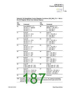
Table 96. ZDI Read/Write Control Register Functions (ZDI_RW_CTL = 16h in
the ZDI Register Write-Only Address Space) (Continued)
Hex
Hex
Value
Command
Value
Command
09
Reset ADL
ADL ← 0
89
8A
Reserved
0A
Exchange CPU register sets
AF ← AF’
Reserved
BC ← BC’
DE ← DE’
HL ← HL’
0B
Read memory from current PC 8B
value, increment PC
Write memory from current PC
value, increment PC
Note: The eZ80 CPU’s alternate register set (A’, F’, B’, C’, D’, E’, HL’) cannot be read directly.
The ZDI programmer must execute the exchange instruction (EXX) to gain access to the
alternate eZ80 CPU register set.
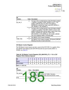
ZDI Bus Control Register
The ZDI Bus Control register controls bus requests during DEBUG mode. It enables or
disables bus acknowledge in ZDI DEBUG mode and allows ZDI to force assertion of the
BUSACK signal. This register must be written during ZDI Debug mode (that is, following
a BREAK). See Table 97.
Table 97. ZDI Bus Control Register (ZDI_BUS_CTL = 17h in the ZDI Register
Write-Only Address Space)
Bit
7
0
6
0
5
0
4
0
3
0
2
0
1
0
0
0
Reset
CPU Access
Note: W = Write-only.
W
W
W
W
W
W
W
W
PS013015-0316
Zilog Debug Interface

 ZILOG [ ZILOG, INC. ]