eZ80L92 MCU
Product Specification
169
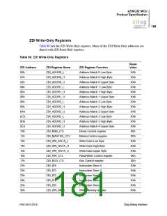
ZDI Read-Only Registers
Table 91 lists the ZDI Read-Only registers. Many of the ZDI Read-Only addresses are
shared with ZDI Write-Only registers.
Table 91. ZDI Read-Only Registers
Reset
Value
ZDI Address
00h
ZDI Register Name
ZDI_ID_L
ZDI Register Function
eZ80 Product ID Low Byte register
eZ80 Product ID High Byte register
eZ80 Product ID Revision register
Status register
06h
00h
XXh
00h
XXh
XXh
XXh
00h
XXh
01h
ZDI_ID_H
02h
ZDI_ID_REV
ZDI_STAT
03h
10h
ZDI_RD_L
Read Memory Address Low Byte register
Read Memory Address High Byte register
Read Memory Address Upper Byte register
Bus Status register
11h
ZDI_RD_H
12h
ZDI_RD_U
17h
ZDI_BUS_STAT
ZDI_RD_MEM
20h
Read Memory Data Value
ZDI Register Definitions
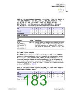
ZDI Address Match Registers
The four sets of address match registers are used for setting the addresses for generating
break points. When the accompanying BRK_ADDRx bit is set in the ZDI Break Control
register to enable the particular address match, the current ZLP12840 address is compared
with the 3-byte address set, {ZDI_ADDRx_U, ZDI_ADDRx_H, ZDI_ADDR_x_L}. If
the CPU is operating in ADL mode, the address is supplied by ADDR[23:0]. If the CPU is
operating in Z80 mode, the address is supplied by {MBASE[7:0], ADDR[15:0]}. If a
match is found, ZDI issues a BREAK to the ZLP12840 placing the processor in ZDI mode
pending further instructions from the ZDI interface block. If the address is not the first op-
code fetch, the ZDI BREAK is executed at the end of the instruction in which it is exe-
cuted. There are four sets of address match registers. They can be used in conjunction with
each other to break on branching instructions. See Table 92.
PS013015-0316
Zilog Debug Interface

 ZILOG [ ZILOG, INC. ]