eZ80L92 MCU
Product Specification
112
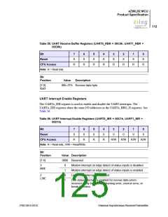
Table 55. UART Receive Buffer Registers (UART0_RBR = 00C0h, UART1_RBR =
00D0h)
Bit
7
X
R
6
X
R
5
X
R
4
X
R
3
X
R
2
X
R
1
X
R
0
X
R
Reset
CPU Access
Note: R = Read only.
Bit
Position
Value
Description
[7:0]
00h–FFh Receive data byte.
RxD
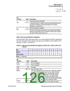
UART Interrupt Enable Registers
The UARTx_IER register is used to enable and disable the UART interrupts. The
UARTx_IER registers share the same I/O addresses as the UARTx_BRG_H registers. See
Table 56.
Table 56. UART Interrupt Enable Registers (UART0_IER = 00C1h, UART1_IER =
00D1h)
Bit
7
0
6
0
5
0
4
0
3
0
2
0
1
0
0
0
Reset
CPU Access
R
R
R
R
R/W
R/W
R/W
R/W
Note: R = Read only.; R/W = Read/Write.
Bit
Position
Value Description
[7:4]
0000 Reserved
3
MIIE
0
1
0
1
Modem interrupt on edge detect of status inputs is disabled.
Modem interrupt on edge detect of status inputs is enabled.
Line status interrupt is disabled.
2
LSIE
Line status interrupt is enabled for receive data errors:
incorrect parity bit received, framing error, overrun error, or
break detection.
PS013015-0316
Universal Asynchronous Receiver/Transmitter

 ZILOG [ ZILOG, INC. ]