eZ80L92 MCU
Product Specification
109
UARTx_BRG_L) and outputs a pulse to indicate the end-of-count. Calculate the UART
data rate with the following equation:
System Clock Frequency
UART Data Rate (bps)
=
16 x (UART Baud Rate Generator Divisor)
Upon RESET, the 16-bit BRG divisor value resets to 0002h. A minimum BRG divisor
value of 0001h is also valid, and effectively bypasses the BRG. A software Write to either
the Low- or High-byte registers for the BRG Divisor Latch causes both the Low and High
bytes to load into the BRG counter, and causes the count to restart.
The divisor registers can only be accessed if bit 7 of the UART Line Control register
(UARTx_LCTL) is set to 1. After reset, this bit is reset to 0.
Recommended Usage of the Baud Rate Generator
The following is the normal sequence of operations that should occur after the ZLP12840
MCU is powered on to configure the Baud Rate Generator:
•
•
•
Set UARTx_LCTL[7] to 1 to enable access of the BRG divisor registers
Program the UARTx_BRG_L and UARTx_BRG_H registers
Clear UARTx_LCTL[7] to 0 to disable access of the BRG divisor registers
BRG Control Registers
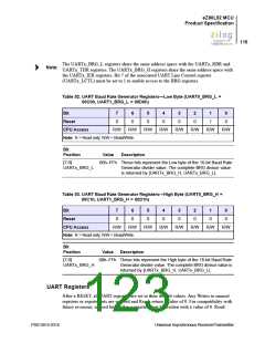
UART Baud Rate Generator Registers—Low and High Bytes
The registers hold the Low and High bytes of the 16-bit divisor count loaded by the pro-
cessor for UART baud rate generation. The 16-bit clock divisor value is returned by
{UARTx_BRG_H, UARTx_BRG_L}, where x is either 0 or 1 to identify the two available
UART devices. On RESET, the 16-bit BRG divisor value resets to 0002h. The initial 16-
bit divisor value must be between 0002h and FFFFh as the values 0000h and 0001h are
invalid, and proper operation is not guaranteed. As a result, the minimum BRG clock divi-
sor ratio is 2.
A Write to either the Low- or High-byte registers for the BRG Divisor Latch causes both
bytes to be loaded into the BRG counter. The count is then restarted.
Bit 7 of the associated UART Line Control register (UARTx_LCTL) must be set to 1 to
access this register. See Table 52 and Table 53. For more information, see UART Line
Control Registers (UARTx_LCTL) on page 115.
PS013015-0316
Universal Asynchronous Receiver/Transmitter

 ZILOG [ ZILOG, INC. ]