eZ80L92 MCU
Product Specification
111
Write attributes, reset conditions, and bit descriptions of all of the UART registers are pro-
vided in this section.
UART Transmit Holding Registers
If less than eight bits are programmed for transmission, the lower bits of the byte written
to this register are selected for transmission. The transmit FIFO is mapped at this address.
You can write up to 16 bytes for transmission at one time to this address if the FIFO is
enabled by the application. If the FIFO is disabled, this buffer is only one byte deep.
These registers share the same address space as the UARTx_RBR and UARTx_BRG_L
registers. See Table 54.
Table 54. UART Transmit Holding Registers (UART0_THR = 00C0h, UART1_THR =
00D0h)
Bit
7
X
6
X
5
X
4
X
3
X
2
X
1
X
0
X
Reset
CPU Access
Note: W = Write only.
W
W
W
W
W
W
W
W
Bit
Position
Value
Description
[7:0]
00h–FFh Transmit data byte.
TxD
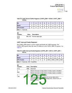
UART Receive Buffer Registers
The bits in this register reflect the data received. If less than eight bits are programmed for
receive, the lower bits of the byte reflect the bits received whereas upper unused bits are 0.
The receive FIFO is mapped at this address. If the FIFO is disabled, this buffer is only one
byte deep.
These registers share the same address space as the UARTx_THR and UARTx_BRG_L
registers. See Table 55.
PS013015-0316
Universal Asynchronous Receiver/Transmitter

 ZILOG [ ZILOG, INC. ]