Microprocessor Control MT312
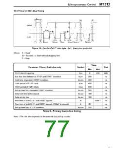
11.6 Primary 2-Wire Bus Timing
t
BUFF
Sr
P
DATA1
CLK1
t
LOW
t
R
t
F
P
S
t
HD;STA
t
HD;DAT
t
HIGH
t
SU;DAT
t
SU;STA
t
SU;STO
Figure 26 - One DiSEqC™ data byte - 0x11 (hex) plus parity bit
Where: S = Start
Sr = Restart, i.e. Start without stopping first.
P = Stop.
Value
Parameter: Primary 2-wire bus only
Symbol
Unit
Min
Max
CLK1 clock frequency
fCLK
tBUFF
tHD;STA
tLOW
0
450
kHz
ns
ns
ns
ns
ns
ns
ns
ns
ns
ns
Bus free time between a STOP and START condition.
Hold time (repeated) START condition.
LOW period of CLK1 clock.
200
200
450
600
200
100
100
HIGH period of CLK1 clock.
tHIGH
tSU;STA
tHD;DAT
tSU;DAT
tR
Set-up time for a repeated START condition.
Data hold time (when input).
Data set-up time
Rise time of both CLK1 and DATA1 signals.
Rise time of both CLK1 and DATA1 signals, (100pF to ground)
Set-up time for a STOP condition.
note 1
tF
20
tSU;STO
200
Table 8 - Primary 2-wire bus timing
Note 1.The rise time depends on the external bus pull up resistor.
77

 ZARLINK [ ZARLINK SEMICONDUCTOR INC ]