Microprocessor Control MT312
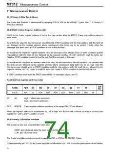
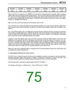
ADDR[7]
VSS
ADDR[6]
VSS
ADDR[5]
VSS
ADDR[4]
VDD
ADDR[3]
VDD
ADDR[2]
VDD
ADDR[1]
VSS
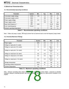
When the MT312 is powered up, the RESET pin 49 should be maintained low for typically 250ms (minimum
100ms) after VDD has reached normal operation levels. This is to ensure that the crystal oscillator and internal
PLL have become fully established and that the internal reset signal is fully clocked into all parts of the circuit.
As the reset pin is pulled high, the logic levels on ADDR[7:1] are latched to become the 2-wire bus address
ADDR[7:1]. ADDR[0] is the R/W bit.
IIN[5:1] are only used for test purposes and should be wired to VSS.
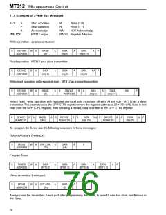
The circuit works as a slave transmitter with the eighth bit set high or as a slave receiver with the eighth bit set
low. In receive mode, the first data byte is written to the RADD virtual register, which forms the register sub-
address.
Bit 7 of the RADD register, IAI is an Inhibit Auto Increment function. When the IAI bit is set high, the automatic
incrementing of register addresses is inhibited. IAI set low is the normal situation so that data bytes sent on the
2-wire bus after the RADD register data are loaded into successive registers. This automatic incrementing
feature avoids the need to individually address each register.
Following a valid chip address, the 2-wire bus STOP command resets the RADD register to 00. If the chip
address is not recognised, the MT312 will ignore all activity until a valid chip address is received. The 2-wire
bus START command does NOT reset the RADD register to 00. This allows a combined 2-wire bus message,
to point to a particular read register with a write command, followed immediately with a read data command. If
required, this could next be followed with a write command to continue from the latest address. RADD would
not be sent in this case. Finally a STOP command should be sent to free the bus.
When the 2-wire bus is addressed (after a recognised STOP command) with the read bit set, the first byte read
out shall be the content of register 00.
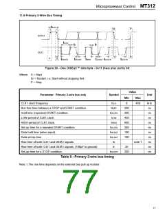
11.4 Secondary 2-Wire Bus for Tuner Control
The MT312 has a General Purpose Port that can be configured to provide a secondary 2-wire bus with full bi-
directional operation. When pass-through is enabled, a transparent connection is made to the tuner. This
innovative design simplifies the software required to program the tuner to only five data bytes.
Pass-through mode is selected by setting register (20) GPP CTRL[B6] = 1.
The allocation of the pins is: GPP[0] pin 44 = CLK2, GPP[1] pin 45 = DATA2.
75

 ZARLINK [ ZARLINK SEMICONDUCTOR INC ]