MT312 Microprocessor Control
11 Microprocessor Control
11.1 Primary 2-Wire Bus Address
The 2-wire bus Address is determined by applying VDD or VSS to the ADDR[7:1] pins. See 11.3 Primary 2-
Wire Bus Interface.
11.2 RADD: 2-Wire Register Address (W)
RADD is the 2-wire register address. It is the first byte written after the MT312 2-wire chip address when in
write mode.
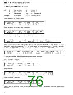
To write to the chip, the microprocessor should send a START condition and the chip address with the write bit
set, followed by the register address where subsequent data bytes are to be written. Finally, when the
'message' has been sent, a STOP condition is sent to free the bus.
To read from the chip from register address zero, the microprocessor should send a START condition and the
chip address with the read bit set, followed by the requisite number of CLK1 clocks to read the bytes out.
Finally a STOP condition is sent to free the bus. RADD is not sent in this case.
To read from the chip from an address other than zero, the microprocessor should send the chip address with
the write bit set, followed by the register address where subsequent data bytes are to be read. Then the
microprocessor should send a START condition and the chip address with the read bit set, followed by the
requisite number of CLK1 clocks to read the bytes out. Finally a STOP condition is sent to free the bus
A STOP condition shall reset the RADD value to 00. For examples of use, see 74.
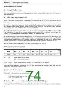
RADD (virtual register, address none)
Def
hex
NAME
ADR
B7
B6
B5
B4
B3
B2
B1
B0
RADD
N/A
IAI
AD6
AD5
AD4
AD3
AD2
AD1
AD0
W
-
B7:
IAI
High = Inhibit auto increment.
Low = Increment addresses.
B6-0:
AD[6:0]
2-wire register address, numbers in the range 0 to 127 are allowed.
When the register address is incremented to 127 it stops and the bus will continue to write to or read from
register 127 until a STOP condition is sent.
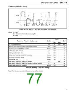
11.3 Primary 2-Wire Bus Interface
The primary 2-wire bus serial interface uses pins:
DATA1 (pin 54) Serial data, the most significant bit is sent first.
CLK1 (pin 53) Serial clock.
The 2-wire bus Address is determined by applying VDD or VSS to the ADDR[7:1] pins.
For compatibility with VP310, the 2-wire bus Address should be 0001 110 R/ and the pins connected as follows:
74

 ZARLINK [ ZARLINK SEMICONDUCTOR INC ]