GP2021
These represent the correlation of the I and Q signals with
the PROMPTand TRACKING codes, over the integration
period. There is no overwrite protection mechanism on
these registers so the data must be read before the next
DUMP.
counter when in Update mode, or after the next TIC if in
PRESET Mode.
The Epoch Counter values are latched on each TIC into
the CHx_EPOCH register. In addition the instantaneous
values are available from the CHx_EPOCH_CHECK
register.
Code Phase Counter
The Code Phase Counter counts the number of half-chips
of generated code and stores this value in the
CHx_CODE_PHASE register on each TIC.
PERIPHERAL FUNCTIONS
The following section describes the Dual UART, RealTime
Clock and Watchdog, Power and Reset Control and
Discrete l/O blocks.
Code Slew Counter
The Code Slew Counter is used to slew the generated
code by a number of half chips in the range 0 to 2047. In
Update mode the slew occurs following the next DUMP. In
preset mode it occurs at the next TIC. All slew operations
are relative to the current code phase. The Code Slew
counter must be written to each time a slew is required.
Dual UART
ADual UART is included for serial communications. It has
two identical blocks, UART_A and UART_B, each
containing separate transmit and receive channels. The
parity and separate transmit and receive baud rate can be
configured independently for each UART. Each uses a
polled processor interface and each transmit and receive
channel has an 8- byte deep FIFO.
During the slewing process the accumulators for the
channel being slewed are inhibited so that the first result
is valid. If a slew is written while a channel is disabled it will
occur as soon as the channel is enabled.
For further information on UARTregisters refer to the Detailed
Description of Registers and Figure 11 (page 28).
Epoch Counter
The Epoch Counters keep track of the number of code
periods over a 1 second interval. This is represented by a
5-bit word for the number of 1ms integration periods (0 to
19), plus a 6-bit word containing the number of 20ms counts
(0 to 49). The Epoch Counters can be pre-loaded to
synchronise them to the data stream coming from the
satellite. This value will be transferred immediately to the
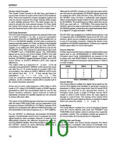
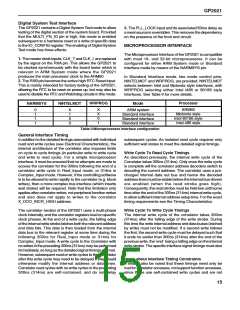
A typical serial data stream is shown in Fig. 6. The Parity
bit is optional and if no parity is selected the time slot for it
is removed from the data stream and the Stop bit follows
immediately after the last data bit in both transmit and
receive directions. Note that the LSB is always preceded
by a Start bit.Table 6 shows possible UART configurations.
START
FIRST
STOP
LAST
D8
D9
D10
D11
D12
D13
D14
D15
P
LSB
MSB
PARITY
(OPTIONAL)
Figure 6 Serial data waveform
Parameter
Start bits
Value
1 bit low
Data bits
Stop bits
Parity
8 bits Logic 0 = low, Logic 1 = high
1 bit High
Odd/even/none
None
Flow control
Transmit FIFO depth 8 bytes
Receive FIFO depth 8 bytes
FIFO speed
Transmit FIFO write rate and Receive FIFO read rate maximum is one byte per 230ns.
The maximum buffer through delay is 2 s.
Data rate
300, 600,1·2k, 2·4k, 4·8k, 9·6k, 19·2k, 38·4k and 76·8k baud. Transmit and Receive
rates individually configured.
Table 6 UART functionality
11

 ZARLINK [ ZARLINK SEMICONDUCTOR INC ]