GP2021
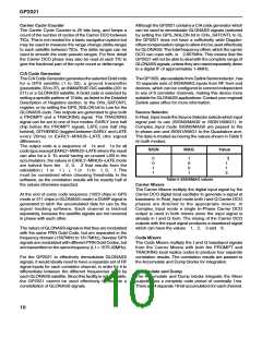
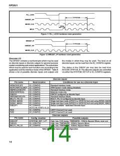
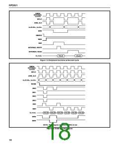
PLL_LOCK
NRESET_OP
MICRO_CLK
4 CYCLES
50ms
MCLK
Figure 11 PLL_LOCK hardware reset generation
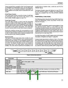
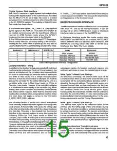
NRESET_IP
NRESET_OP
MICRO_CLK
4 CYCLES
Figure 12 NRESET_IP hardware reset generation
Discrete l/O
The GP2021 contains a numberof pins which may be used
as discrete inputs or discrete outputs for general purpose
system monitoring and control applications.The actual pins
which may be used for each function vary according to the
application and the interface mode of the GP2021. Table 8
shows a list of possible discrete inputs and outputs and
the modes in which they may be used. The level on all
discrete inputs can be read from the IO_CONFIG register.
The status of the DISCIP pin may also be read from
ACCUM_STATUS_B. The discrete outputs are controlled
via either the SYSTEM_SETUP or IO_CONFIG registers.
Discrete inputs
Conditions for use as a discrete input
Standard Interface mode.
Pin name
Read location
IO_CONFIG
NRW/DISCIP3
NOPC/NINTELMOT IO_CONFIG
ARM System mode (debug disabled).
NMREQ/DISCIP2
NBW/WRPROG
DISCIO
NBRAM/DISCIP4
MULTI_FN_IO
SIGN0, MAG0
SIGN1, MAG1
DISCIP1
IO_CONFIG
IO_CONFIG
IO_CONFIG
IO_CONFIG
IO_CONFIG
IO_CONFIG
IO_CONFIG
IO_CONFIG
ACCU M_STATU S_B
IO_CONFIG
IO_CONFIG
Standard Interface mode.
Motorola mode only.
DISCIO configured as discrete Input.
Standard Interface Mode.
MULTI_FN_IO configured as discrete input.
Single real input mode (GP2010 or GP2015) front end using SIGN0, MAG0.
Single real input mode (GP2010 or GP2015) front end using SIGN1, MAG1.
Always available - dedicated Discrete Input.
RXA
RXB
UART Channel A not used.
UART Channel B not used.
Discrete outputs
Possible outputs
Pin name
Config. location
DISCOP
DISCIO
SYSTEM_SET_U P
IO_CON FIG
High, low, CH0 dump, TIMEMARK, 100kHz Square Wave, scan out.
High, low, TIMEMARK, 100kHz Square Wave.
MULTI_FN_IO
IO_CONFIG
High, low, TIMEMARK, 100kHz Square Wave.
Table 8 Discrete input/output configuration
14

 ZARLINK [ ZARLINK SEMICONDUCTOR INC ]