R
QPRO XQ4000E/EX QML High-Reliability FPGAs
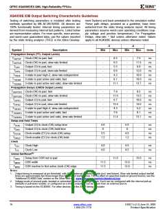
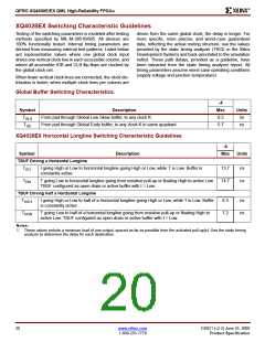
XQ4028EX Switching Characteristic Guidelines
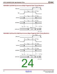
Testing of the switching parameters is modeled after testing
methods specified by MIL-M-38510/605. All devices are
100% functionally tested. Internal timing parameters are
derived from measuring internal test patterns. Listed below
are representative values where one global clock input
drives one vertical clock line in each accessible column, and
where all accessible IOB and CLB flip-flops are clocked by
the global clock net.
driven from the same global clock, the delay is longer. For
more specific, more precise, and worst-case guaranteed
data, reflecting the actual routing structure, use the values
provided by the static timing analyzer (TRCE in the Xilinx
Development System) and back-annotated to the simulation
netlist. These path delays, provided as a guideline, have
been extracted from the static timing analyzer report. All
timing parameters assume worst-case operating conditions
(supply voltage and junction temperature)
When fewer vertical clock lines are connected, the clock dis-
tribution is faster; when multiple clock lines per column are
Global Buffer Switching Characteristics.
-4
Symbol
Description
Max
9.2
Units
ns
T
From pad through Global Low Skew buffer, to any clock K
GLS
T
From pad through Global Early buffer, to any clock K in same quadrant
5.7
ns
GE
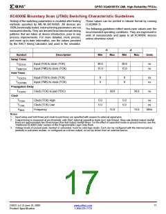
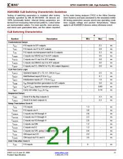
XQ4028EX Horizontal Longline Switching Characteristic Guidelines
-4
Symbol
Description
Max
Units
TBUF Driving a Horizontal Longline
T
I going High or Low to horizontal longline going High or Low, while T is Low. Buffer is
constantly active.
13.7
14.7
ns
ns
IO1
T
T going Low to horizontal longline going from resistive pull-up or floating High to active Low.
TBUF configured as open-drain or active buffer with I = Low.
ON
TBUF Driving Half a Horizontal Longline
T
I going High or Low to half of a horizontal longline going High or Low, while T is Low. Buffer
is constantly active.
6.3
7.2
ns
ns
HIO1
T
T going Low to half of a horizontal longline going from resistive pull-up or floating High to
active Low. TBUF configured as open-drain or active buffer with I = Low.
HON
Notes:
1. These values include a minimum load of one output, spaced as far as possible from the activated pull-up(s). Use the static timing
analyzer to determine the delay for each destination.
20
www.xilinx.com
DS021 (v2.2) June 25, 2000
1-800-255-7778
Product Specification

 XILINX [ XILINX, INC ]