R
Spartan-II FPGA Family: Functional Description
Multiple FPGAs in Slave Serial mode can be daisy-chained
for configuration from a single source. The maximum
amount of data that can be sent to the DOUT pin for a serial
daisy chain is 220-1 (1,048,575) 32-bit words, or 33,554,400
bits, which is approximately 25 XC2S200 bitstreams. The
configuration bitstream of downstream devices is limited to
this size.
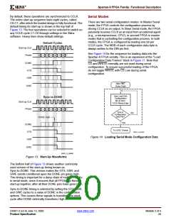
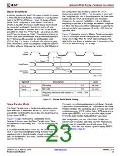
Slave Serial Mode
In Slave Serial mode, the FPGA’s CCLK pin is driven by an
external source, allowing FPGAs to be configured from
other logic devices such as microprocessors or in a
daisy-chain configuration. Figure 15 shows connections for
a Master Serial FPGA configuring a Slave Serial FPGA
from a PROM. A Spartan-II device in slave serial mode
should be connected as shown for the third device from the
left. Slave Serial mode is selected by a <11x> on the mode
pins (M0, M1, M2).
After an FPGA is configured, data for the next device is
routed to the DOUT pin. Data on the DOUT pin changes on
the rising edge of CCLK. Configuration must be delayed
until INIT pins of all daisy-chained FPGAs are High. For
more information, see "Start-up," page 19.
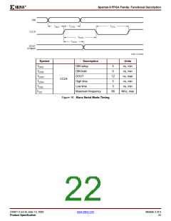
Figure 16 shows the timing for Slave Serial configuration.
The serial bitstream must be setup at the DIN input pin a
short time before each rising edge of an externally
generated CCLK.
3.3V
3.3V
2.5V
3.3V
3.3V
2.5V
3.3 K
M0 M1
M2
VCCO
M0 M1
M2
VCCO
VCCINT
VCCINT
DOUT
DOUT
DIN
CCLK
Spartan-II
(Master Serial)
Spartan-II
(Slave)
Vcc
CCLK
CLK
DATA
CE
PROM
DIN
CEO
PROGRAM
PROGRAM
DONE
RESET/OE
DONE
INIT
INIT
GND
GND
GND
PROGRAM
Notes:
DS001_15_060608
1. If the DriveDone configuration option is not active for any of the FPGAs, pull up DONE with a 330Ω resistor.
Figure 15: Master/Slave Serial Configuration Circuit Diagram
DS001-2 (v2.8) June 13, 2008
Product Specification
www.xilinx.com
Module 2 of 4
21

 XILINX [ XILINX, INC ]