R
Spartan-II FPGA Family: Functional Description
Configuration
Table 8: Spartan-II Configuration File Size
Configuration is the process by which the bitstream of a
design, as generated by the Xilinx software, is loaded into
the internal configuration memory of the FPGA. Spartan-II
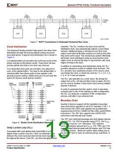
devices support both serial configuration, using the
master/slave serial and JTAG modes, as well as byte-wide
configuration employing the Slave Parallel mode.
Device
XC2S15
XC2S30
XC2S50
XC2S100
XC2S150
XC2S200
Configuration File Size (Bits)
197,696
336,768
559,200
781,216
1,040,096
1,335,840
Configuration File
Spartan-II devices are configured by sequentially loading
frames of data that have been concatenated into a
configuration file. Table 8 shows how much nonvolatile
storage space is needed for Spartan-II devices.
Modes
It is important to note that, while a PROM is commonly used
to store configuration data before loading them into the
FPGA, it is by no means required. Any of a number of
different kinds of under populated nonvolatile storage
already available either on or off the board (i.e., hard drives,
FLASH cards, etc.) can be used. For more information on
configuration without a PROM, refer to XAPP098, The
Low-Cost, Efficient Serial Configuration of Spartan FPGAs.
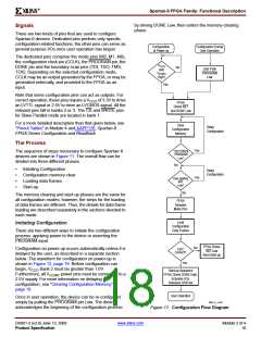
Spartan-II devices support the following four configuration
modes:
•
•
•
•
Slave Serial mode
Master Serial mode
Slave Parallel mode
Boundary-scan mode
The Configuration mode pins (M2, M1, M0) select among
these configuration modes with the option in each case of
having the IOB pins either pulled up or left floating prior to
the end of configuration. The selection codes are listed in
Table 9.
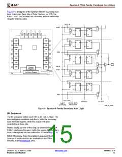
Configuration through the boundary-scan port is always
available, independent of the mode selection. Selecting the
boundary-scan mode simply turns off the other modes. The
three mode pins have internal pull-up resistors, and default
to a logic High if left unconnected.
Table 9: Configuration Modes
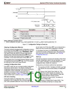
Preconfiguration
CCLK
Configuration Mode
Pull-ups
M0
0
M1
0
M2
0
Direction
Data Width
Serial DOUT
Master Serial mode
No
Out
1
Yes
Yes
Yes
No
0
0
1
Slave Parallel mode
Boundary-Scan mode
Slave Serial mode
Notes:
0
1
0
In
N/A
In
8
1
1
No
No
0
1
1
Yes
No
1
0
0
1
0
1
Yes
No
1
1
0
Yes
1
1
1
1. During power-on and throughout configuration, the I/O drivers will be in a high-impedance state. After configuration, all unused I/Os
(those not assigned signals) will remain in a high-impedance state. Pins used as outputs may pulse High at the end of configuration
(see Answer 10504).
2. If the Mode pins are set for preconfiguration pull-ups, those resistors go into effect once the rising edge of INIT samples the Mode
pins. They will stay in effect until GTS is released during startup, after which the UnusedPin bitstream generator option will determine
whether the unused I/Os have a pull-up, pull-down, or no resistor.
DS001-2 (v2.8) June 13, 2008
Product Specification
www.xilinx.com
Module 2 of 4
17

 XILINX [ XILINX, INC ]